ATmegas are nifty little things. You can get them very cheap and they are very versatile to do simple things like controlling a LED, reading out a sensor, logging the data, controlling a display, etc.
For these simple applications the ATmega8 is usually sufficiently good. This chip only has 8 kB of flash data. But for small applications given above this is more than enough. For programs requiring more memory you can go for a higher numbered ATmega like the ATmega328.
Nowadays you can find ATmegas (usually the 328-kind) on Arduino boards. These require a certain voltage input of 5 – 12 V and are not necessarily power friendly. The required input voltage means that if you want to run it on batteries you have to combine it in such a way to obtain at least close to 5 V. This can be tricky if you want to build something compact and do not necessarily need a lot of power.
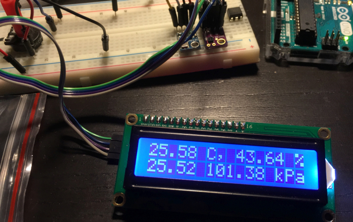 Figure 1: Typical use of an ATmega microcontroller. Sensors measure out the temperatures, relative humidity and the ambient pressure.
In this blog I will succinctly describe how to setup an ATmega8 at low power with the Arduino IDE. Also, I will describe the process of running the ATmega8 with only 2 AAA batteries or even a button cell. The process includes underclocking the ATmega8 from 16 MHz to 1 MHz using the internal oscillator. In the end this reduces power consumption considerably and allows the ATmega8 to run at lower voltages.
Burning the bootloaderI bought empty ATmega8s from Ebay. These need to be loaded by a bootloader first. To do this I will use an Arduino UNO as an In-circuit Serial Programmer (ISP). We assume you used the Arduino UNO before on your computer and installed the Arduino IDE. To setup the ISP we need to
- First, connect the Atmega8 to an Arduino UNO to program the device as follows
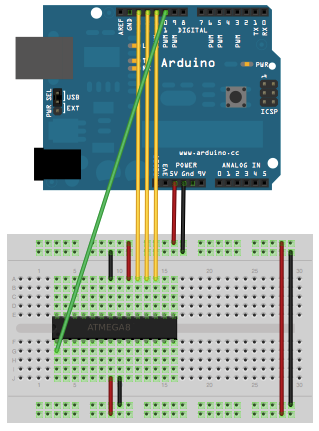
Note the orientation of the microchip. The semi-circle notch is in this case on the left and determines pin orientation. - In the Arduino IDE add
https://raw.githubusercontent.com/carlosefr/atmega/master/package_carlosefr_atmega_index.json
to ‘Additional Board Manager URLs:’ under ‘Preferences’. This will locate the package needed for the ATmega8 microchip. - To install the board go to
‘Tools’ -> ‘Board: (..)’ -> ‘Boards Manager’,
then do the following
‘Type’ -> ‘Contributed’ -> ‘Barebones ATmega …’ -> Install - Next, we need to setup the Arduino UNO as ISP.
Select the UNO board, the proper COM port and Programmer (for me AVRISP mkII) in the ‘Tools’ menu.
These are the defaults for running code from your Arduino UNO. - Select the ‘ArduinoISP’ sketch from ‘File’ -> ‘Example’.
This should be installed by default in the Arduino IDE.
Upload this to the UNO. - For burning the bootloader we need to change some things under ‘Tools’:
‘Programmer’ -> ‘Arduino as ISP’
‘Board’ -> ‘Atmega8’
‘Clock’ -> ‘1 MHz (internal)’ (You can select any ofcourse, I select 1 MHz for low power and low voltage workings) - We can now burn the Bootloader under ‘Tools’ -> ‘Burn Bootloader’.If this is not working the wiring of the Arduino UNO to the Atmega8 could be wrong. Double check it. Adding a 10k resistor to pin 1 and 5V might help.
Or, the ATmega8 needs a 16 MHz oscillator as default. This is the case if there already is a bootloader in. So add that (only needed for the first time) and some capacitors and try to burn the bootloader again with the above options. After this works you can remove the oscillator.
- You can check if everything works fine by adding a LED to one of the digital out pins and running the ‘Blink’ example. The settings from previous steps (setting up ISP) must remain the same.
If everything works congrats! You have now setup the ATmega8 with as few as possible components and low power to use for small and efficient projects! The ATmega8 can be run from low voltages such as 3V only requiring 2 AA/AAA. With additional low-power libraries it is possible to set the chip to standby to allow it to run even off a button cell for a decent amout of time! (‘Decent amount’ can be calculated by getting the charge stored in the battery (usually mAh or Ah) and measuring the current of the ATmega when active.)
Going to even lower voltagesBy running the ATmega8 at low voltages the brownout detection comes into play. By disabling this the ATmega8 can be run from voltages down to 1.8V. You first have to think if this is okay for your project. The supply voltage means that any device(s) you connect will only get the same voltage max. A high signal will also correspond to this value instead of the usual 5V.
In order to remove brownout detection, we have to change the ‘fuse settings’ of the ATmega8:
- Install WinAVR (if not installed).
- In the command prompt type:
avrdude -c arduino -p m8 -P COM4 -b19200
This can be different if you use a different programmer (-c arduino), a different microchip (-p m8) or a different port (-P COM4). This will tell us if the selected programmer and microchip is correct and working.
- Type:
avrdude -c arduino -p m8 -P COM4 -b 19200 -v
to see some more stuff and check the fuse settings.
Now, if there is some problem with ‘Device signature’. You can ‘hack’ it by editing ‘avrdude.conf’ (search in you AVR program dir) for your given microchip signature. I changed the signature under ATmega8 to correspond to my conflict and commented the original line. Not sure why it differed, but this helped. This might not needed though.
- Use this awesome website http://www.engbedded.com/fusecalc to calculate the fuse settings for Brown-out detection disabled. Mine were: 0xE1 and 0xCD. You can also check what settings the current fuse values corresponds to. A check would be to see if it is indeed set to 1 MHz clock. You can check the corresponding change to the fuse settings by just unchecking the mark for brownout detection.
- Now we write these fuse settings with avrdude in the command prompt as:
avrdude -c arduino -p m8 -P COM4 -b19200 -U lfuse:w:0xe1:m -U hfuse:w:0xcd:m -F
The -F might not be needed.
- Check if the fuse settings are correctly set using avrdude -c arduino -p m8 -P COM4 -b 19200 -v
You can now check if you can go as low as 2V for the power supply. For example, you can check using the ‘Blink’ example if the LED still blinks to see if the ATmega8 is working.
If you got everything to work: congratulations! Now use your ATmega8 for something efficient!
Advertisements Share this: