Notes on managing outputs in Stage Box – Digital Splitters
Whether Audio Splitter or Passive Stage Box, Active or Digital, some optimal connection solutions as needed are:
In the case of position in groups of the Digital Stage Box – Splitter, remember the groups configuration In / Out seen in the article Stage Box – III (fig. 1).
Fig. 1 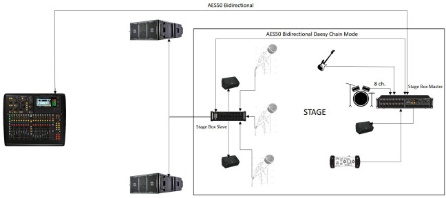
n.b. In the case of using the Digital Stage Box – Splitter in one place without having an audio mixer stage, it is advisable to take the signal for stage monitor from the Stage Box Master. This is to have lower latency possible in a stage monitor (crucial to ensure the musician to keep time and not feel an annoying delay), while the signal of the P.A. System always from Stage Box Master if available additional output lines or from other Stage Box Slave.
Fig. 2 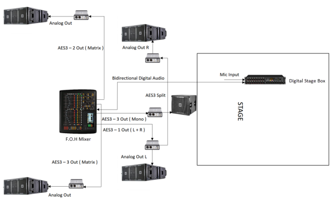
n.b. Very often, however, the AES3 line especially in digital audio mixer of not high level is one and fixed with LR output, so in this case it is limited in the digital connection of the outputs, but it has always more quality that with other configurations in which there are provided sections of analog path, mono and matrix lines must be so taken from the Digital Stage Box or analog outputs of the audio mixer same depending on the configuration (fig. 3).
Fig. 3 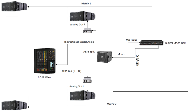
N.B. When you have to link more final power together, it is recommended to test whether the overall latency of all final linked in order to determine whether the increased latency caused an impoverishment of the final audio quality (due to compression, alteration of the frequency response, increased THD% by jitter and intrinsic noise of the electronic circuitry (PLL), and many other parameters). In some cases (quality systems) even 3 – 4 final linked together via AES3 do not create a high overall latency to perceive an annoying delay and impoverishment of the audio signal. Alternatively, digitally link the first final power input connections point to point with the output connections of the digital audio mixer) and link to analog level in the next bridge (analog daesy chain).
A very good solution is to use multichannel final power (from 4 up), so as to be able to use less link to connect the same audio speakers, compared to having final single power, but also dual-channel.
Many manufacturers precisely for this reason, provide for their audio speakers a series of digital power amplifiers with digital inputs and outputs from 4 channels up.
If the distance between Stage Box – Splitter and P.A. sound system as may be the tower delay is higher than that between the audio mixer and delay tower may be more qualitative take the output directly from the audio mixer (fig. 4).
Fig. 4 
n.b. If you have more AES3 outputs and are fully customizable you can use the same method for sending the signal to the stage monitors (one line and 1 converter for each monitor). In general many more output lines there are, even more so if with different domains and standard and the more it will be necessary to qualitative purposes and phase use analyzers and processors to calibrate to the best the time delay of the audio signal, such that each output has the same delay time (will then be seen in other arguments the techniques and tools necessary to calibrate the audio systems).
Some Digital Stage Box – Splitter present AES3 outputs (calls also AES / EBU) directly on the Stage Box- Splitter (fig. 5).
Fig. 5 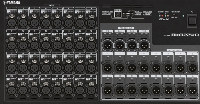
Other solutions (The most qualitative between all as the signal travels in the digital domain until the final stage without the introduction of analog connections) but much more challenging (as it then requires routing programming) and even more expensive are those o enter directly the digital input (AES3 – MADI – DANTE – AES50 – Other protocols) provided in some types of digital crossover and final power of the latest generation (fig. 6 – 7).
fig. 6 ( Crossover with input AES3 ) 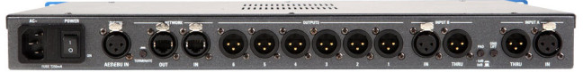
fig.7 (Power Amp with input AES3)
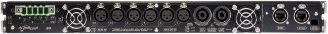
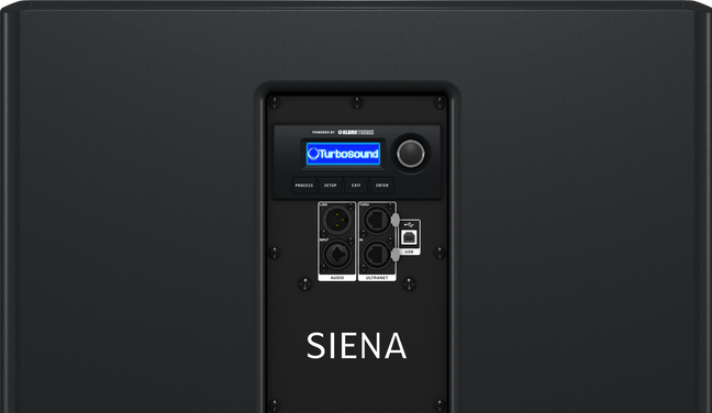
fig. 8 ( Sound System with input )
For synchronous standard (AES50 and MADI) realize this type of complete digital domain configuration is more complex and articulated, in that the synchronous system needs point to point connections or daesy chain, in order to maintain the synchronism, then you would need to patch systems manufactured and prepared for this type of connection, and that in any case they should do head to a single router-patch that sorts the different outputs of the digital audio signal hen to be configured via the routing interface. This then leads to a limitation in the process of creating a complex signal path (any power amp or processor at any position in a given environment should still be connected to the main router patch).
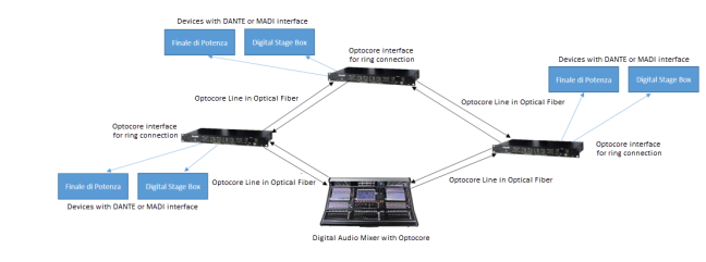
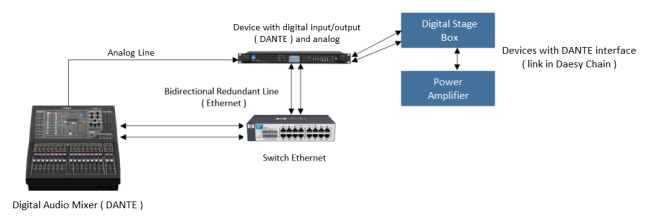
Especially for complex installations is more practical and qualitatively useful to use an isochronous connection standard or asynchronous as the DANTE or RAVENNA that as seen for digital Stage Box carryover in figure 9 offering a type of star connection allows to make independent of each line output so as to be able to position any Digital Stage Box – Splitter near to each group of P.A. sound system with nowhere to create long signal bridges (fig. 10), (it is possible to use more than one router-patch to create more sorting points in a given environment ). We’ll look at the operation of the audio networks in more detail).
Fig. 9 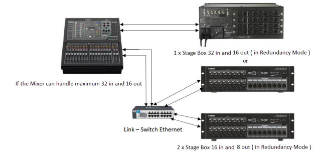
Fig. 10 
Through special software on PC and via the same interface of the digital audio mixer you can control the routing in / out of the signals present in the ethernet switch and Digital Stage Box – Splitter.
Fig. 11 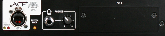
Fig. 12 
n.b. When there are more slots in which they can be lodging more interfaces, these slots are sometimes called Port A, Port B …. connectable with the name of the type of interface, but the function is always the same. In case there isn’t the name of the protocol type accepted is fundamental to inform. For ADAT interfaces it is critical to know how many channels the mixer can manage to send and receive digital signals under the protocol, as there are interfaces ADAT 8, 16, 32 channels. In general, an ADAT connection port to a maximum of 8 channels and is not bidirectional for which it will take both the interface for the inputs that that for the outputs, if provided more channels there will be multiple connections in the same interface, like the one in Figure 13 that for handle 32 tracks has 4 input connections and output connections 4.
Fig. 13 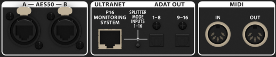
Fig. 14 (example of configuration with direct out to ADAT from Stage Box – Splitter for Digital Stage Mixer).
Fig. 14 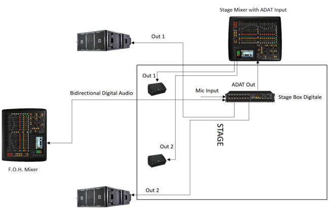
Fig. 15 (example of configuration with direct out to ADAT from Stage Box – Splitter for Multitrack Recorder).
Fig. 15 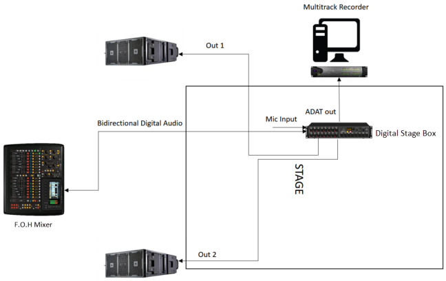
It’s also possible to enter into an audio mixer which has interfaces ADAT exploiting the input connections for the sampling of the input signals of the Digital Stage Box and those output to be sent to a multitrack recorder to have a more precise control over gain and any other parameters on the signal to be sent to the recorder (fig. 16).
Fig. 16 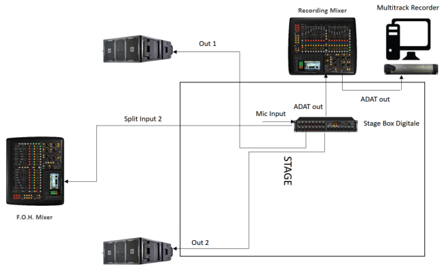
n.b. Digital protocols such as DANTE, AES50, MADI allow remote control of the pre-amplifiers present in Digital Stage Box – Splitter directly from the digital audio mixer, the ADAT standard does not.
Fig. 17 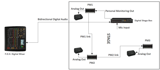
Fig. 18 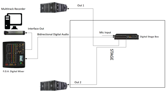
To date the digital standards, considering the most commonly used DANTE, AES50, MADI, may allow the independent sending of all input signals to the digital audio mixer, distributed over one or more connections according to the maximum quantity portable by a single connection and for sections up to 50 meters and more if we convert the fiber optic signal, and then more channels and more distances compared to older ADAT standard, as well as a better quality for lower latency and better components used. This allows, limited by the capacity of the same digital audio mixer in use to create additional configurations like the one in Figure 19.
Fig. 19 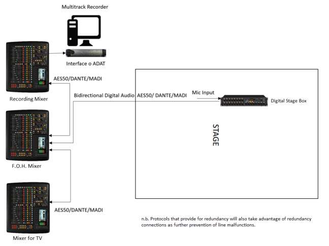
Other
For a configuration Daisy Chain of the Digital Stage Box, any digital audio mixers should generally be connected as in the example in Figure 20.
Fig. 20 
In this example, we used the AES50 protocol with denominated connections A and B, but you can also find connections with numbers, and even more than 2 connections as seen, suitably to be connected. The same discourse worth for the connection of several audio mixers in star configuration (fig. 21).
Fig. 21 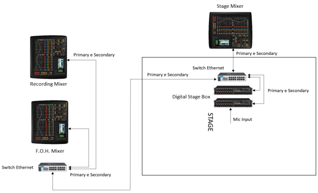
In the example shown in Figure 20 a possible protocol in star configuration as that DANTE, port redundant signal called Primary and Secondary or other names defined by the manufacturer, both to be connected to the Ethernet Switch. The configuration via DANTE protocol also allows the connection in Daesy Chain of the Stage Box (through the same interface configurations) but both depend on the other (more than anything else for convenience), it tends to separate them in order to maximize the possibilities and routing choices.
n.b. Through all of these configurations just seen and the use of an appropriate routing for the management of inputs and outputs it is possible to create a larger control surface (for example, use the first 24 channels on the first mixer and the channels 24-48 on the second mixer, having common or separate outputs), it is possible to split sometimes with the help of special audio interfaces implemented in the digital audio mixer the same signal on more than one mixer in order to have a backup. Other mixers allow you to link with proper protocol and proprietary cable.
Even the Dante protocol or any P2P protocol can carry AES / EBU lines albeit poorer quality as the synchronous direct connection between an outlet and an inlet. This is possible as the clock of the AES / EBU line is regenerated arrival of the signal buffer.
Some considerations on registration
As for the signal path to be sent to a multitrack recorder, this can be taken directly from the Splitter -Digital Stage Box (which comes as a Direct Out output, so before the amplification stage, so you can record the various signals independently of the levels set for the live event, so that they can be properly and qualitatively managed in the studio), or directly from the Digital Audio Mixer (usually through a special audio interface, and most of the time the signal shows post Gain controls, then with the signal level recorded depending on the gain levels defined in the live mix, less qualitative procedure).
n.b. In some cases, digital audio mixers (often through choice of user-defined settings), if the gain control from the mixer is isolated from that of the Splitter – Digital Stage Box (so it is not enabled for remote control), you can send on the output via audio interface in the mixer the signal as Direct Out so not dependent on the gain levels set on the mixer. This procedure can be made even more by connecting an Analog Splitter – Stage Box directly to the digital audio mix inputs (if present), allows for a high quality gain on the Recording part (due to the independence of recording gains between live recording and mixing), but a poorer impoverishment from the Splitter – Digital Stage Box (due to the remote control of pre- amplifiers, and thus increase the noise and noise of the sound from the long path of the audio signal “from splitter – stage box to mixer” with a very low signal level.
The best solution is always the first, so the Direct Out pick of the signal from the Splitter – Digital Stage Box.
The signal output from the Mixer or Splitter – Digital Stage Box as well as the one seen in the previous configuration examples may have the most varied protocols, if the recording interface allows it to enter directly with the output protocol (figure 22). If it does not allow it, a protocol converter will need to be introduced (figure 23).
Fig. 22 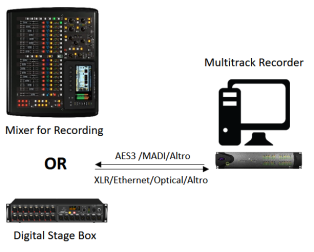
Fig. 23 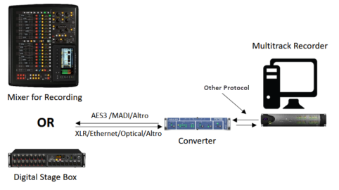
Generally, considering multiple standards of digital audio protocol (such as AES3, MADI, AES50, DANTE), the interface of recording and PC is almost always done via USB or FireWire or proprietary link.
As we will see in more detail when we talk about digital audio, if using RAVENNA audio protocol this will be able to enter the PC directly ( in the Ethernet connection) without the use of external interface (ensuring absolute quality due to the absence of additional device such as the audio interface) (figure 24).
Fig. 24 
Mixed configurations
If instead you have an analog mixer, a digital mixer or more in both categories and a Stage Box – Digital Splitter, it is always good distance use digital mixer (eg for position F.O.H and / or Broadcast) and analog near the Digital Stage Box – Splitter (such as a mixer stage and / or recording), so as to take in the digital domain the longer routes and in the analog domain the shorter ones.
As seen in topic Stage Box, recently they were developed models of Digital Stage Box – Splitter Hybrid (fig. 25) with which is possible interfacing digital audio mixer and analog audio mixer used the same Digital Stage Box – Splitter (fig. 26).
Fig. 25 
Fig. 26 
In this example, it’s clear how the distribution of the analog split takes place towards the stage audio mixer, whilst the F.O.H. audio mixer is connected remotely in the digital domain.
There are several variants of Hybrid Stage Box, even with Socapex multi connector for analog and / or digital transport (especially for AES3 lines).
Other
If you don’t have the need or opportunity to purchase a Hybrid Stage Box, to interface the analog stage mixer, you can also use the D / A converters (which can convert to analog the digital standard in use) that convert in analog each digital channel so that it can be interfaced with the analog audio mixer inputs. With Digital Stage Box that present multiple protocols available for sending the audio signal or of a split, is definitely easier to decide and choose the best and most suitable converter to use for their own needs (fig. 27).
Fig. 27 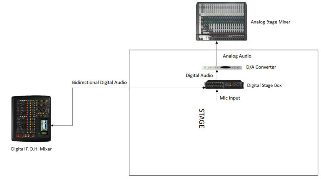
Signal Split by Digital Audio Mixer
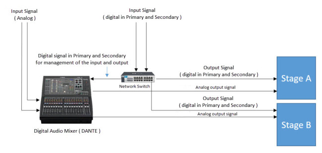
We then defined as to split the input or output one or more signals the Dante protocol may take advantage of the network router by sending for which a single signal to multiple outputs (limited by the number of outputs and inputs portable from the router and from the digital mixer itself), then although as we will see more complex in the management of inputs and outputs compared to AES50 and MADI is more suitable for managing routing complexes such as having to manage inputs and outputs to and from two or more different locations as may be 2 or more stages in which are present musical groups such as to be able to receive and send separate signals making independent the 2 or more stages or receives and send the same signal to all and 2 or more stages, always using a single mixer (fig. 28 – 29).
Fig. 28 (example with analog and digital input and various analog and digital outputs considering also the redundancy, the analog signal is always connected directly to the mixer of analog inputs or to an external stage box then digitally connected to the network router), the digital connection to the switch is in parallel or star mode).

Fig. 29 (example with multiple analog and digital inputs and analog and digital outputs redundancy considering also, the analog signal is always connected directly to the mixer of analog inputs or to an external stage box then digitally connected to the network router), (even in this case the digital connection to the switch is in parallel or star mode).
AES50 and MADI are limited in the split and management of different signals depending on the number of available connections. For example, the AES50 is often required by connection AES50 A and AES50 B, the B is generally as seen, used for the signal split from the stage audio mixer, but it can also be used as a Split in the management of inputs and outputs to and from the digital audio mixer (fig. 30 – 31).
Fig. 30 (example with analog and digital input and various analog and digital outputs, the analog signal is always connected directly to the mixer of analog inputs or to an external stage box then digitally connected on AES50 A or B), in star or parallel mode.
Fig. 30 
Fig. 31 (example with multiple analog and digital inputs and analog and digital outputs, the analog signal is always connected directly to the mixer on analog inputs or to an external stage box then digitally connected on AES50 A or B), always in star or parallel mode.
Fig. 31 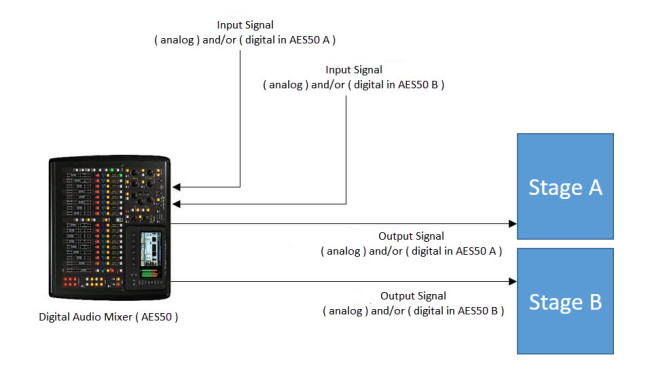
n.b. By routing from digital mixer or remote-control software, it is possible to decide which and how to manage the sending of audio signals, so if maintain reception areas and sending separated or whether to send the same signals to all outputs.
The star or parallel connection mode provides many advantages over the series or daesy chain, the key advantage is the ability to independently handle two situations simultaneously, not possible in side chain, since as seen is dependent on the other, the other advantages are the fact that if either of the two Splitter – Digital Stage Box lose signal (example missing current, sudden signal interruption or broken) the other continues to work, in the case of side chain mode if the first Splitter – Digital Stage Box stops working the second plugged into series will not work accordingly as it does not receive plus clock and signal. Another advantage is the maintenance of a lower latency, since as seen in side chain mode, all the latencies of the bridge-connected devices are added.
Point-to-point and star configuration are configurations to obtain the highest possible quality for minimum latency induced and full speed bandwidth utilization of the device.
This is why the star or parallel connection mode is always preferred to others.
Other Modes
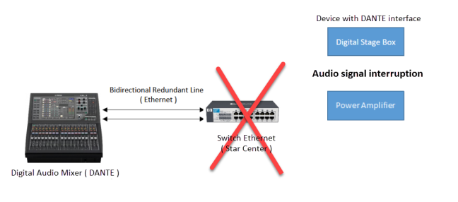
As we will see when we talk about digital audio and audio networks, there are also other connection modes to create signal routing in a digital network. Most commonly used is ring or ring mode. Ring mode is useful when you need absolute redundant control. Star mode includes a star center provided by a network switch or audio interface such as those seen in this argument (eg the interface in the audio mixer) (figure 32) multichannel to which all switches (nodes) or audio devices distributed in various areas (Splitter – Digital Stage Box, power amplifiers, etc …), In this case, if the switch / central interface (star center) stops working, the entire system is interrupted and is therefore not 100% reliable if it is cheaper than a ring configuration (figure 33).
Fig. 32 (example of star configuration)
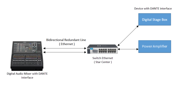
Fig. 33 (example of breaking star center)
In a ring configuration, all the switches or audio interfaces are serially connected to one another (daesy chain), and the last device must be connected to the first, in the appropriate switch / interface inputs that provide a type of ring connection. By closing the circle, and if a switch / interface along the line is interrupted, the other switches / interfaces present before or after the interrupted one continue to operate (as the system automatically receives the signal from a way or from the ‘other, always insulating the malfunctioning system and allowing everything else to continue running). Therefore, the system is more reliable than a star, point-to-point and simple daesy chain, and it is recommended to use it in critical situations, as it can better handle the redundancy of the various signals, having absolute security (limited only by breakage of the master device to which the ring is connected for sending (opening) and returning (closing) (fig. 34 – 35).
Fig. 34 (example of ring configuration)
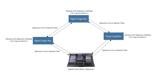
Fig. 35 (example of ring signal interruption)

A ring configuration such as daesy chain is less qualitative than point-to-point and star as it increases the overall latency of the circuit and reduces the bandwidth available for each connected device (half to every doubling of elements connected to the daesy chain).
n.b. Each protocol and then the audio interface that supports it can be configured according to its limits, so as we will see, some protocols may and must be configured to function correctly to star, daesy chain, and other ring. An example of AES50, MADI and DANTE can be configured point-to-point, star, and in some cases more modern in daesy chain, other protocols such as Optocore and some versions of Ether sound can be connected in addition to in just-viewed ring modes. As you can easily guess, interfaces with ring configurations are more complex and costly.
A protocol like DANTE, MADI, AES50 that provide (always giving the other two only in some interfaces) a redundancy connection, ring link is not possible, since even reverting to redundancy this would not work and you would only a common connection to Daesy Chain, since redundancy only activates when the main signal is missing, while in connections made by ring configuration such as OPTOCORE, the connection is always active and always takes the signal to then handle the signal flow based on where the interruption is.
When choosing which protocol and type of configuration it is necessary to evaluate the need:
- QUALITY (synchronous protocol, plugged into point-to-point or star-linked as AES50 or MADI, OPTOCORE only if the interface in the device is native, and therefore does not convert to another protocol before sending, Optocore is another synchronous protocol)
- EXPANDIBILITY AND ARTICULATED SYSTEMS (Isochronous protocol plugged into point to point or star like DANTE, RAVENNA)
- SECURITY (protocol synchronous or isochronous depending on whether you need more quality or more expandability, attached to ring as OPTOCORE)
n.b. Never close the ring in a network switch that is not predisposed to handle a ring configuration (e.g. any network switch used in the computer), this would cause a loop and therefore a resonance phenomenon and signal feedback at distortion levels with the risk of breaking the various connected devices, not only on it but on all switches and interfaces that are connected together (figure 36).
Fig. 36 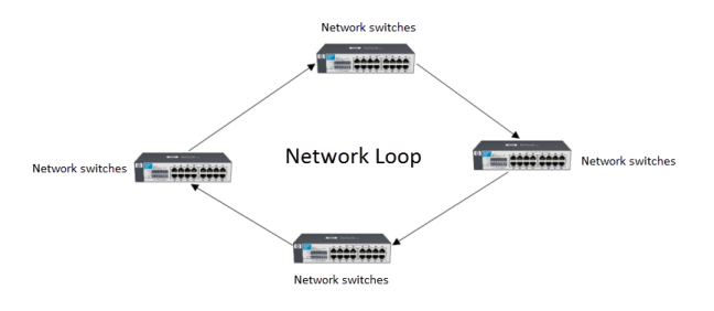
For bi-directional network protocols such as DANTE and RAVENNA, do not connect multiple dual-cable switches, thinking of sending both the signal and the redundancy, as the output from the switch would only have a copy of the incoming audio signal (and the redundancy only activates when the signal is missing from the main connection) and then creates a loop in the system (figures 37 to 38), unless it is not possible through the software to decide that the dual cable connection port is enabled only when activates the redundancy connection.
Fig. 37 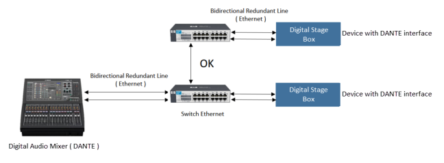
Fig. 38 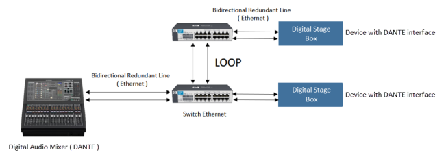
There are switches for redundant bridge linking that use special connections separate from those used to split the audio signal to be sent to the various devices.
n.b. As can be seen from Figures 37 and 38 if the devices such as Stage Box, Power Ends, etc. also have a redundant interface, it is useful to connect both connections to the switch so that in case there is a break of the signal from the device is ready and active redundant.
Another principle to follow in using network switches for linking protocols traveling on ip (network) as the DANTE is to use fewer possible bridge switches, as it increases latency and even possible signal transfer errors between one switch and the other.
As for the type of connection for protocols traveling on fiber optic and mono-bipolar cable (BNC-XLR), they always present a double connection (one IN and one OUT) (fig. 39 if on separate cables) (fig. 40 if they are Opticalcon) so they are not bidirectional, since with a conductor you can only use a transport line for the audio signal, while when the signal is transmitted to multipolar lines (ethernet cables) (fig. 41) then it is possible to determine a bi-directional signal transport, as some poles will be used for the input of the input signal and others for the output.
Fig. 39 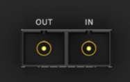 Fig. 40
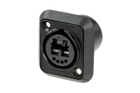
Fig. 41 
If there is a redundancy connection for example for the fiber optic or BNC signal path then there must be a double IN-OUT connection (fig. 42), while for bidirectional ones there is only one additional Ethernet connection for redundancy (fig 43).
Fig. 42 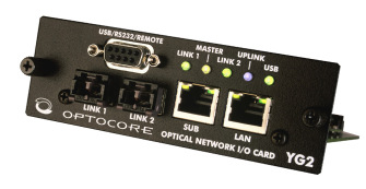
Fig. 43 
In Figure 42, an interface can be implemented in compatible devices in which Link 1 and Link 2 are the two fiber optic connections (double connection each, which as seen from the fiber requires an In and one Out cable) used for the realization of a ring configuration, from Link 1 starts the ring and Link 2 closes.
For connection of power amplifiers, Stage Box – Digital Splitters or hardware devices that support the connection of these digital protocols, as seen in the examples in this article, ring mode is not used, since to fully exploit security given by this type of configuration, as seen it is necessary to close the ring on the switch / starting interface (usually the primary control matrix, such as the digital audio mixer or switch to which its digital lines are connected to provide signal separation), so that the whole redundant signal path is protected. Inserting interfaces and / or switches to close the ring on devices like Splitter – Digital Stage Boxes, Power amplifiers, etc. would make little sense as it would limit the system’s potentiality.
For complex systems such as the use of network switches in isochronous protocols such as DANTE, to optimize expanding routing, it is recommended as mentioned above to place a switch for each zone or group of Splitter – Digital Stage Boxes, power amplifiers and / or devices that communicate on this protocol, and switch the star signal to every single device, then connect all other switches (few if possible, as mentioned above) to the other areas projected in the project phase (Figure 44), or even better a star switch configuration (Figure 45) ( 2 bridge switches “that star center and the one directly connected” is definitely better than a daesy chain series).
Fig. 44 
Fig. 45 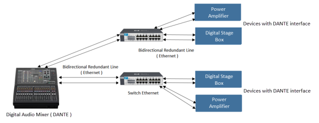
n.b. If the mixer has a multichannel interface recommended, use the mixer as star center (fig.45).
If you have an interface for ring connection, if it is considered appropriate to use the switches for a ring configuration (figure 46)
Fig. 46 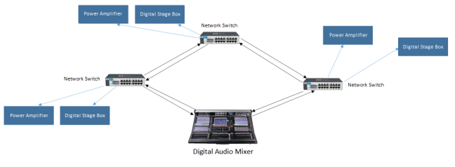
To accomplish any of these configurations, each connected device must then have an interface capable of transmitting and receiving signal in the date configuration. For example, for Digital Stage Box with DANTE Protocol Interface, it is not possible to create a ring configuration as it provides as seen only 2 connections, that of the primary channel and the redundant signal. To make a ring, the interface should provide another double connection to receive the ring closure, which, as mentioned, can be found in master devices such as audio mixers or external interfaces. If this is not the case or even one of the connected devices does not allow this passage then the signal path is interrupted and has a limited configuration.
Each device (Splitter – Digital Stage Box, power amplifiers etc.) can be connected in series or daesy chains or as said for better quality in star mode to switch (for network-based protocols like DANTE) or the same interface from which all the audio signal (eg audio mixer or control matrix, for synchronous protocols such as AES50 and MADI) is managed.
For a ring configuration, if devices do not have their own interface for this type of configuration or even more dialogue on different protocols than that used for ring configuration, you can use external rack interfaces (figure 47) that allow you to create a ring signal path for the corresponding protocol and then offer the signal on a protocol suitable for the type of device to which it is connected (figure 48).
Fig. 47 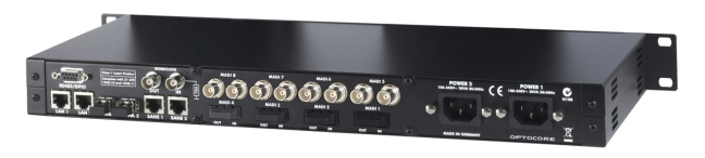
Fig. 48 ( example of configuration for using a protocol as a link and another sorting protocol ).
In Figure 47, an interface on external hardware that allows a fiber optic or ethernet network configuration (Link 1 and Link 2) on OPTOCORE protocol, then can handle the audio signal in input and output on MADI protocol.
It is also possible to create mixed configurations or ideally put a switch / interface for each single device to be handled (for maximum control with minimum errors), but it would be an expensive solution and would take a lot more time for its wiring and configuration to achieve a small increase in security since interrupting a switch interrupts only the device connected to it. And in addition it would lead to a degradation of quality especially if all these switches were connected in daesy chain.
Using interfaces such as those OPTOCORE that allow any type of configuration is more expensive but very useful and versatile.
The figure 47 also allows a bridge connection type with other interfaces of the same manufacturer (via SAME port) so that it can expand signal routing by obtaining multiple inputs and outputs of the same or different protocol
Finally, there are also interfaces that allow to make a redundant connection type even on an analog connection, so that if the digital connection and its possible redundancy interrupt the system switches automatically to the analog connection (figure 49) (figure 50).
Fig. 49 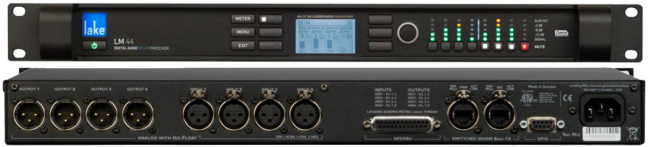
Fig. 50 ( esempio di configurazione con protocollo DANTE )
n.b. The configuration in Daesy Chain does not provide for redundancy, so if the device to handle the redundant analog allows using one or more multichannel interfaces, use a Stella configuration, otherwise Daesy Chain configuration is the only possible one.
In Figure 51 a graphical representation of a complex routing project proposed by digico.biz for linking audio interfaces to a live event situation.
Fig. 51 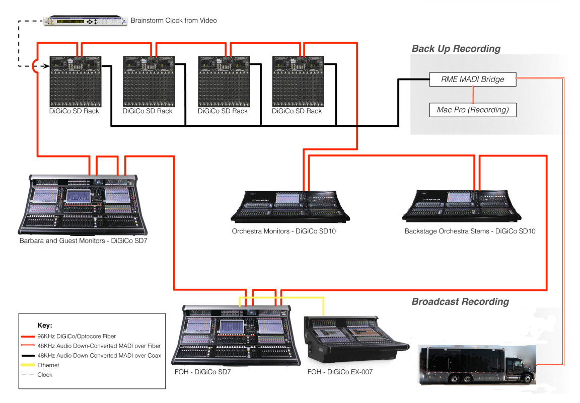
By examining this articulated path signal we can see that the main matrix either the front house mixer (FOH Digico SD7), in this case with a spare (FOH Digico EX-007) connected with an Ethernet network cable, from the SD7 starts the ring up on protocol OPTOCORE 96 kHz fiber optic, enters in the OPTOCORE input of the stage mixer (Barbare and Guest Digico SD7), always comes out at level of the OPTOCORE protocol from the stage mixer and enters the first Digital Stage Box (SD Rack) with OPTOCORE input, always for ring configuration. In Daesy Chain are then connected all the Digital Stage used for the event and from the last one is taken the signal always on OPTOCORE protocol to be sent to the mixer for the tracking of the orchestra present in this type of live event (Orchestra Monitors Digico SD10 (so you can take a little work on stage sound (using two phonics) and concentrate the two groups of monitor lines independently and even more safely (Band – Orchestra). From the mixer of the orchestra will always be connected on OPTOCORE bridge with a mixer used to control the orchestral stems (Backstage Orchestra Stems Digico SD10) (in practice there is a speaker that pre-mixes the orchestra so as to send to the FOH mixer already a pre-mixing performed (generally to section groups or the entire orchestral mix) and take some stress and work on the FOH Engineer (given the innumerable channels and instruments that would in this case be mixed, even more of 90 ch.) The output of the mixer for the orchestral stems always on protocol OPTOCORE in optical fiber is sent in closing the ring to the room mixer (FOH Digico SD7 from which the ring has started).
In this situation, there is also the presence of a Mobile Studio Broadcast (example for registering and broadcasting the live event). By taking a copy of split from the signal of Digital Stage Box, trough the output connections on MADI protocol at 48-Khz in star configuration towards MADI (RME MADI Bridge) matrix, a copy of the signal is sent on parallel Fiber optic to an audio interface connected to a computer for a copy of multitrack audio recording (Mac Pro Recording) and the other copy always on Optical Fiber at the Broadcast station for recording and broadcasting.
n.b. For routing and project simplicity, you always try to make a group configuration, first the matrices (one way and the other) (defining the master (FOH) and the slave (all the rest)) and then all the devices (Stage Box, power amps, etc …). Fiber optic connections point to a possible positioning of devices at distances greater than 100 m, or in any case at the performance level, the fiber optic offers superior performance to the ethernet cable for signal transmission speed from one point to another.
This example also uses an external clock generator (Brainstorm Clock) for audio-video synchronization.
Another solution to increase the degree of protection against possible disadvantages (always at the expense of final audio quality) is to use, for example, an external digital matrix (Fig. 47) that smears the In / Out audio signals to the control devices main and spare. For example, in figure 52 we have a matrix to which two audio mixers are used as main and the other as Spare, and the matrix (spare line) set to enable in case of main line failure (sometimes it is necessary to click a button to handle the matrix patch to change the signal routing between the main mixer and the Spare).
Fig. 52 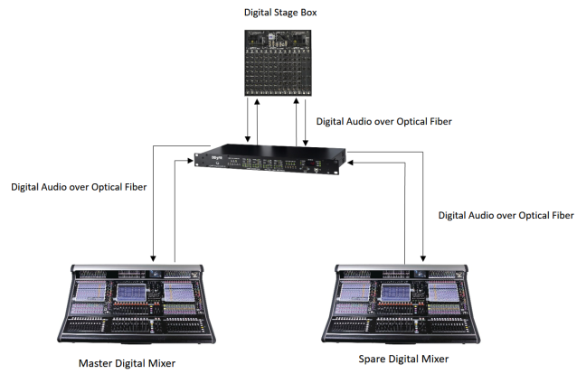
Considering the example in figure 52, the audio output signals from the Splitter – Digital Stage Box in analog domain (eg MADI on fiber optic) and from it, came presorted-split the signals to be sent to the main digital audio mixer and the Spare. The Splitter – Digital Stage Box is connected to its turn in ring configuration with the matrix, which in this case both the matrix and the stage box are equipped with an interface that allows this type of configuration by increasing the level of redundancy and therefore security. You create a double ring configuration.
In this case, the Spare is used as if it were ring closure in a ring configuration.
It is a configuration that can also be used to increase redundancy level and then security in protocols that do not provide ring configuration (AES50, MADI, DANTE), thanks to the fact that you can use OPTOCORE example matrices for linking to ring and then pick up the converted signal in the protocol of interest for sending to the main mixer and the Spare (which could also be of different protocols).
It can be useful if the device allows it to use a Digital Splitter – Stage Box that also makes it matrix, which allows it to send different digital lines to output on a different protocol so as to create a ring configuration as shown in figure 53.
Fig. 53 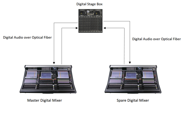
In this case you will see how to properly configure the Digital Stage Box with the two digital audio mixers based on the routing options offered by the various devices.
Mixers that include connection in Spare via Bridge between the main and the Spare as in the example in figure 51, if the mixer supply skip, also the Spare skip, while in this case it is possible to isolate the problem to an external matrix.
Generally sending a signal to a Spare is always a copy of what comes from the Splitter – Digital Stage Box or any other digital device to which the main mixer is connected and is always done immediately after the interface power supply used for split, so if the mixer stops working at any point before the power supply (usually dual PSU), the Spare continues to operate by managing inputs and outputs independently.
Surely, the solution is better through using an external matrix, though more expensive and less practical, much used in Broadcast.
n.b. In this type of configuration (figs. 52-53) it is always better to use either the clock from the Digital Stage Box (if single) or an external clock generator if there are more than one Digital Stage Box or there are more stations where they arrive different audio signals from different Digital Stage Box to synchronize together, this is because if the master clock is the main audio mixer, if it skip, the spare does not receive the clock anymore because in order to function correctly it will have to be placed in slave mode and then it will not work, but if there are more than one stage Box as seen would work one copy of the other (if in Daesy Chain), or if connected to star all others would not receive the clock and therefore would not work. An alternative is also to use the matrix clock if it allows and is connected to all the input and output devices considered in the project.
Other on Splitters and Summings:
Splitters and Summings – I ( Splitter Types, Analog Passive Splitters and their usage )
Splitters and Summings – II ( Active Analog Splitters and their uses, Digital Splitters )
Splitters and Summings – IV ( Synchronization and Word Clock, Adders )
Advertisements Share this: