The SBD shock absorbers had to disperse a lot of the kinetic energy of landing aircraft, minimizing the chance that the airplane accidentally “bounce” back into the air. (This is a key requirement for the carrier-based planes). For such a characteristics you need a relatively long working span between the free (i.e. unloaded) and the completely compressed (i.e. under max. load) strut piston positions. Indeed, you can observe that the Dauntless landing gear legs are much longer in the flight than in their static position on the ground (Figure 80‑1):
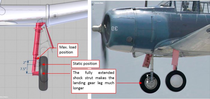 Figure 80-1 The fully extended shock strut
The working span of the SBD shock strut piston was about 10” long, while the difference between the static and the free (extended) piston positions was about 7.5”.
In the most of the aircraft the landing gear retracts with the shock struts fully extended. When I tried to do such a thing with the Dauntless landing gear, as in the Figure 80‑1, I discovered that it definitely does not fit its recess in the wing! (Figure 80‑2):
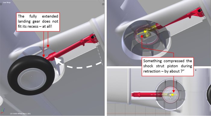 Figure 80-2 Conclusions after fitting the fully extended landing gear into its wing recess
It seems that there was something that compressed SBD landing gear during retraction by about 7”. In the case of the Republic P-47 (which landing gear leg shortened during retraction by 9”), such a thing was widely discussed as an exceptional achievement of its designers. However, nobody even mentioned that the same issue was already resolved several years earlier by the Northrop/Douglas SBD team.
The SBD landing gear leg was made shorter during retraction by compressing its shock strut piston. This “compressing” mechanism starts with the cable that pulls the piston upward. The cable is attached to a quadrant, which rotation is controlled by the rail, fixed to the wing spar (Figure 80‑3):
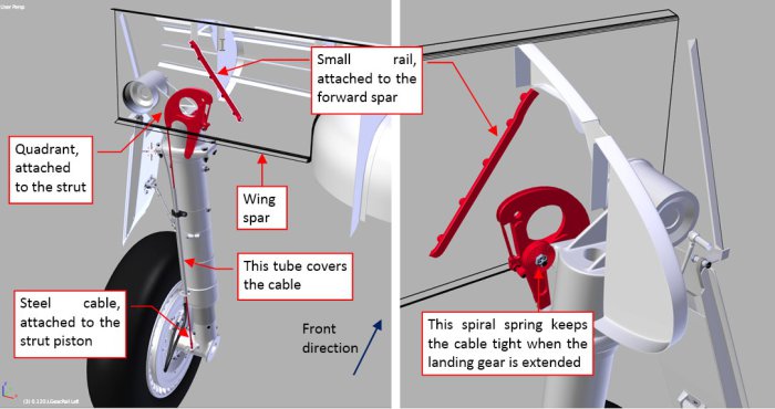 Figure 80-3 Shock strut compression mechanism
An additional spiral spring, attached to this quadrant (Figure 80‑3), tightens the cable when the landing gear is extended. In this landing gear position the spring “freely” rotates the quadrant, just following the shock strut piston movements (Figure 80‑4):
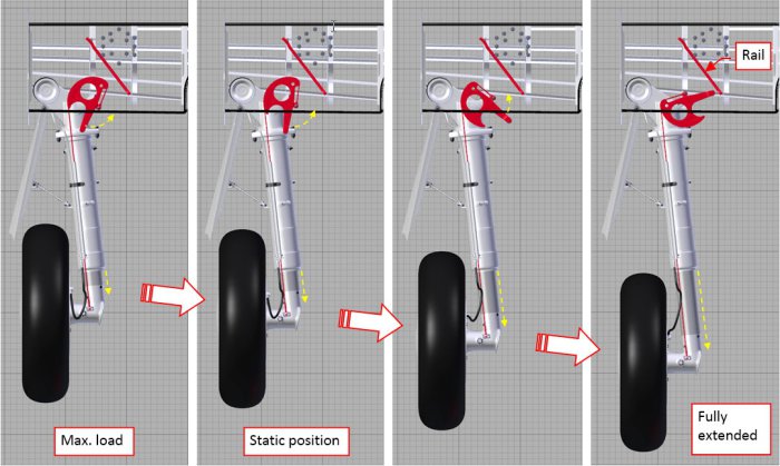 Figure 80-4 Quadrant “idle” movements (landing gear extended)
(You can also see how it works in this short video sequence). Note that this spring ensures that in the fully extended (free) position of the landing gear the tip of the quadrant arm nearly “touches” the rail.
This is the starting position for the piston compression. During the retraction the quadrant rotation axis is elevated upward, while its arm is dragged along the rail (there is a small roller on its tip). In the effect, the quadrant rotates, pulling the cable that compresses the shock strut piston (Figure 80‑5):
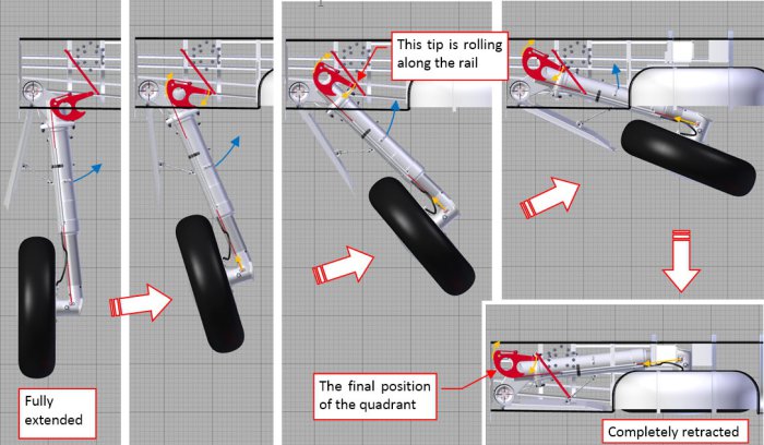 Figure 80-5 Compressing the shocking strut during landing gear retraction
You can also see how it works in this short video sequence. (Note that in this video the path of the quadrant arm tip is not perfect. This is the result of a relatively simple real-time rigging. Anyway, it gives the general idea how this mechanism works).
I also recreated the inner details of the landing gear recess (Figure 80‑6):
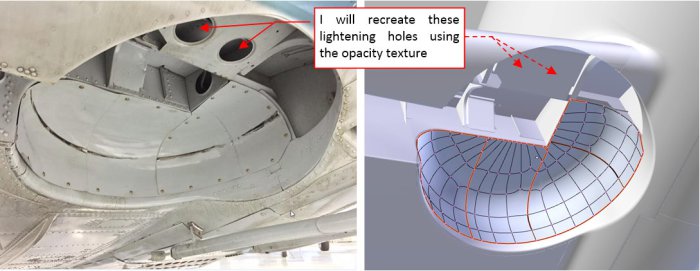 Figure 80-6 The inner details of the landing gear recesses
During the modeling phase I already recreated two spars and two main ribs in the wheel bay. Now I refined their shape, following the available photo reference. I added also the remaining ribs as well as the stringers and the covers (at the rear part of the bay).
As you can see in the picture above, I did not model the lightening holes: as in the case of the wing flaps, I recreated them using textures (Figure 80‑7):
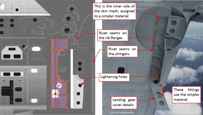 Figure 80-7 Textured details of the wing recess
I unwrapped meshes of all these new wing structure elements into the available space on the UV layouts that I used in the outer skin material (B.Skin.Camouflage, refined in my previous posts). The Navy painted the inner space of this wing recess in the same color as the wing bottom surfaces, so there was not any problem in assigning the B.Skin.Camouflage material to these objects. As you can see in the picture above, I also recreated the internal reinforcements of the landing gear cover. The inner side of the aircraft skin is covered with a generic material, named B.Skin.Details.Bottom. (It is assigned to the second material slot of the wing skin mesh, and set in the Material Index Offset field of its Solidify modifier). This simpler material is intended for the smaller details, and uses exclusively the generic, procedural “noise” textures for the dirt/ref effects. Thus it does not require any time-consuming UV unwrapping. In the figure above I used it also in the cover fittings. I only have to remember to alter the basic color of this simpler material when I switch to another camouflage scheme. (In the future, I will also create a similar material for the details on the upper surfaces – it will only differ in the basic color).
Because this B.Skin.Details.Bottom material has no regular bump map, I had to recreate more landing gear details “in the mesh”. In particular, I had to add the bolts (and nuts) visible on the reference photos. I created each of them as a separate object (Figure 80‑8):
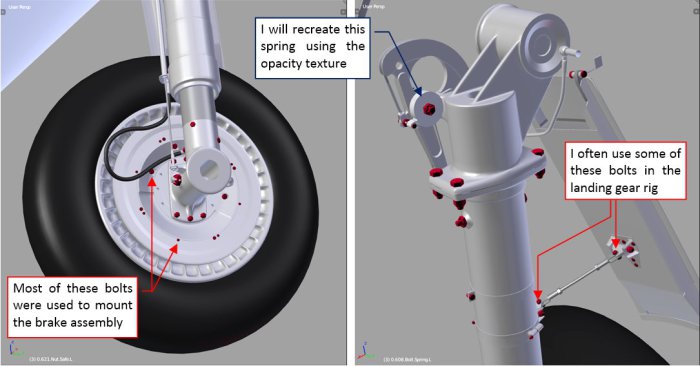 Figure 80-8 Recreating bolts
All these bolts are clones of a few basic original bolt meshes (one with the octagonal head, others with the flat one). Among these originals there are also two or three variations of the bolt length. By default these bolt meshes are covered with a generic “steel” material. When I needed to “paint” them into different color, I alter their material assignment. (In such a case, I had to switch them into the object – based material mode).
Sometimes some of these bolt objects are also useful as the reference objects in the rigging, but I will discuss it in the next post.
I also like to have a look at the retracted landing gear inside the wing structure. When you can see these two assemblies together, suddenly the reason for some strange features of the particular rib or spar shape becomes clear (Figure 80‑9):
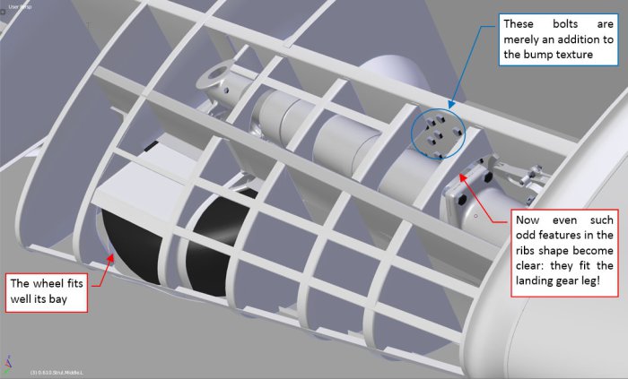 Figure 80-9 Retracted landing gear inside the wing structure
In Figure 80‑9 you can also see a couple of bolts forming an octagonal group on the rear spar. In general, I recreated most of the bolts and rivets on this spar using the bump texture. However, this was a special case: in the original airplane these bolts had quite large heads. What’s more, they were placed on a “stack” of two subsequent panels. I simply run out of the available grayscale of the bump texture in this particular place, thus I decided to recreate these “topmost” details in the mesh. (Just an exception from my general modeling tactics of using the textures as often as possible).
Figure 80‑10 shows the complete landing gear in the open position, the shock strut fully extended:
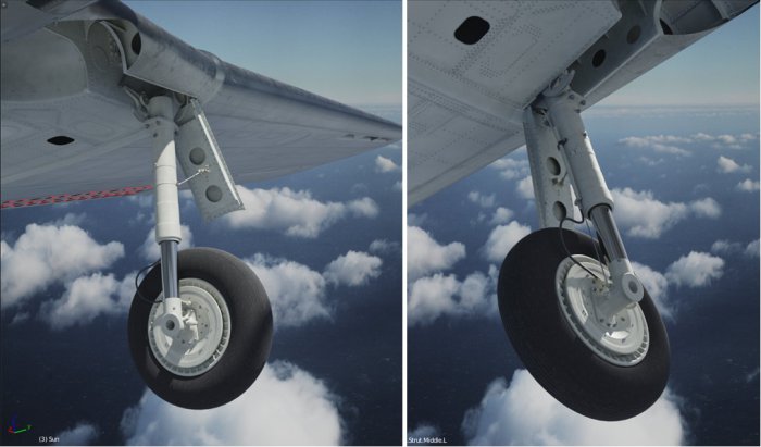 Figure 80-10 Test render of the completed landing gear
The decision to use a simpler materials that do not require UV-mapping has certain disadvantages. The most important of them is that I am not able to paint the small stains around the landing gear bolts and other kinds of the local dirt. But this is just the consequence of the level of details that I assumed for this model.
I have to reveal that this project has a certain deadline: I promised a local modelers’ magazine to deliver detailed SBD scale plans and a couple of color profiles in January 2018. Thus currently I am focusing on the external details, because I have to recreate them to the end of this year. It includes the landing gear and a simpler version of the engine (not intended for the extreme close-ups). When it will be done, later in 2018 I will recreate the cockpit interior, as well as the detailed engine compartment and wing flaps mechanism. This more enhanced version of this model will be intended for a SBD monograph (a book). I will publish it much later.
Among the materials that I have to deliver in winter 2018 I will not enclose any close-up pictures of the landing gear or other details, thus I can use the simpler materials here. However, in such a harsh light as in Figure 80‑10 the elements covered by the B.Skin.Details.Bottom material seem too “clean”. I will definitely work on this issue, increasing the contrast of its “noise” textures to give these landing leg and brake disk a more “dirty” look.
In the next post I will describe how I rigged this landing gear. (I will describe building a kind of “virtual mechanism” that allows me to extend/retract the undercarriage using a single slider. I already used it, making the video sequences presented in this post).
In this source *.blend file you can evaluate yourself the current (i.e. non-rigged) version of this model.
Advertisements Share this: