In this blog, we will explore the topic of interrupts. We will briefly cover the definition and concept of an interrupt, as well as how the CPU handles interrupts. We will then study two types of interrupts – hardware and software interrupts.
What is an Interrupt?In a computing context, an interrupt is a signal from an I/O device to notify the CPU that an event has occurred, and that it requires the CPU’s immediate attention. Because the CPU is connected to multiple peripheral devices, such as the keyboard, hard disk and network card, it is inevitable that the CPU be interrupted at some point. Simple actions such as the click of the mouse or the press of a key on the keyboard will cause an interrupt to occur. The CPU would need to service this interrupt (in a routine known as the Interrupt Service Routine or ISR) and perform the necessary action(s) before returning to its prior task.
Interrupts are an efficient means of using the CPU’s resources because the CPU only performs a task when requested to. An alternative to this is polling in which the CPU continuously checks an external I/O device for its readiness to perform a data transaction. If the device is not ready, the CPU will continue to wait and check on the device periodically. Once the device is ready, the CPU will proceed with the transaction. This is, of course, highly inefficient. It would be better to let the CPU perform other worthy tasks, and only service notifications from external devices when required to rather than continuously checking on them.
How the CPU Handles Interrupts.In this section, I will describe the interrupt handling operations of the Intel 8086 microprocessor as a specific example. Other CPUs will have different means of handling interrupts. Hence from this point onwards, whenever “CPU” is mentioned, it refers to the 8086.
The CPU handles interrupts in a similar manner to how programs handle function calls. When an instruction execution cycle is completed (refer to my previous blog for more information), the CPU checks if an interrupt request has been issued. If so, and if it decides to service the interrupt, it will perform a series of actions.
The following diagram illustrates the actions taken by the CPU, before and after the ISR. Each numbered step will be explained in more detail in the sections below.
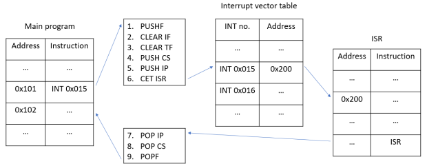
Steps 1 to 6 in the example diagram above are taken before the ISR is executed. They are performed as part of the INT instruction, which represents an interrupt being issued.
- Step 1 : The contents of the flag resister are pushed onto the stack. This is to preserve the flag status of the current program, as the flag register may change during the ISR.
- Step 2 : The interrupt flag is disabled (IF = 0). By disabling the interrupt flag, the CPU can perform an ISR without being interrupted and sidetracked by other incoming interrupts.
- Step 3 : The trap flag is disabled (TF = 0). This prevents the ISR program from stopping after each instruction finishes.
- Note : The trap flag is used by the debugger for stepping onto program lines. See this stackoverflow post for more information.
- Step 4 : The contents of the CS register are pushed onto the stack.
- Step 5 : The contents of the IP register are pushed onto the stack. This, combined with the previous step, preserves the memory address of the next instruction of the current program (in this example, the address 0x102), which will serve as the return address.
- For more information on the CS and IP registers, see the following links : 1 2
- Step 6 : Control is transferred to the memory address storing the ISR. The program looks up a table known as an interrupt vector table (IVT). The IVT is similar in concept to the index pages of a book. Just as index pages map key words to specific pages of a book, the IVT maps interrupt numbers to their starting addresses (i.e the starting addresses of individual ISRs).
- In our example diagram, the interrupt number is 0x15. According to the IVT, the start address of the ISR for interrupt 0x15 is 0x200. Hence the starting address of the ISR we want to invoke is at 0x200.
- This, combined with the previous two steps, is functionally similar to the CALL instruction. Also note that different ISRs have different starting addresses in the IVT, similar to how different functions in a program have different starting addresses.
The steps here are part of “preserving” the current state of the program, similar to the actions taken during a function call (e.g. the return address of the calling program is saved on the stack, the original base pointer is saved on the stack, etc.). Upon completion of these steps, the program corresponding to the ISR is executed.
A short note regarding the CS and IP registers : The CS and IP registers were widely used in the old days when programs were run in a 16-bit OS (viz today’s 32-bit and 64-bit systems). An example of a 16-bit OS is Windows 3.1 and Windows 95. In short, memory addresses were limited to 16-bits. This was the case even if the CPU already uses 32-bits for addressing memory. Hence, to be able to access the full range of 32-bit addresses, the OS uses the CS (code segment) register together with the IP to form a 32-bit address.
Post-ISR Actions.Steps 7 to 9 in the diagram are taken upon returning from the ISR. The final instruction of the ISR is IRET, which serves as a return call back to the original program. The steps explained here are performed as part of the IRET instruction.
- Step 7 : The contents of the IP register are popped from the stack and restored in their original location.
- Step 8 : Same goes for the contents of the CS register. This, combined with the previous step, restores the return address in the relevant registers.
- Step 9 : Same goes for the contents of the flag register. This restores the flag status of the program.
These steps effectively restore the program to its original state before the interrupt was serviced. The program then continues from where it had left off.
Interrupts vs Calls.Interrupts are functionally similar to function calls, but they differ in certain ways.
For instance, when an interrupt is issued, the flag register contents are saved on the stack, and the trap and interrupt flags are reset. These do not occur during a function call.
Another difference is that an ISR returns to the main program via the IRET instruction (instead of RET). While RET only removes the CS and IP register contents from the stack, IRET performs the additional step of popping the flag register contents off the stack.
The Interrupt Vector Table and ISRs.The IVT and the ISRs that they point to are located in RAM and are implemented by the OS. There is a distinct advantage in having the IVT and the ISRs implemented by the OS. That is, they are always upgradeable.
For example, ISRs can be improved with each new OS release. The addresses of ISRs associated with individual interrupts can be replaced dynamically.
How the IVT Maps Interrupts to ISRs.The 8086 microprocessor has 256 interrupt types (from INT 0 to INT 255), each corresponding to a 4-byte address value in the IVT. This means that 1024 bytes (256 x 4) of RAM are dedicated to storing the starting address values of ISRs. The addresses 0x0000 to 0x03FF are dedicated to storing these address values.
Mapping each interrupt to its IVT entry is simple. The interrupt type number (the number attached to the INT instruction, e.g. for INT 0, 0 is the type number) is multiplied by 4 to obtain the starting memory address of the IVT entry. For example, if INT 1 is issued, the corresponding IVT entry starts at address 0x0004. If INT 2 is issued, the corresponding IVT entry starts at address 0x0008.
Each IVT entry contains the starting address of the relevant ISR. From there, control is passed to said address to begin execution of the ISR.
The following diagram illustrates the mapping process :
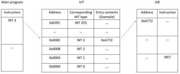
In this example diagram, the main program issues an INT 3. The relevant IVT entry is looked up via multiplying 3 by 4, which will get 12 (or 000C).
The memory block starting from address 0x000C to the next entry address contains the value 0xA772, which is the starting address of the relevant ISR. Control is hence passed to address 0xA772, and the ISR begins executing.
Hardware Interrupts.Hardware interrupts, as the name suggests, are raised by external hardware devices. They are asynchronous and can occur at any time. When interrupts occur, the CPU is notified via a dedicated pin that services interrupt requests. In the Intel 8086 microprocessor, it is called the INTR pin.
For example, when a key is pressed on the keyboard :
- The keyboard issues an interrupt.
- The interrupt is sent to the CPU via the INTR pin.
- The CPU invokes the relevant ISR : in this case, the Keyboard ISR.
- At the end of the ISR, the CPU returns to the original program it had been executing earlier.
Issuing a hardware interrupt is also known as an interrupt request or IRQ.
The Interrupt Controller.As mentioned earlier, the CPU is connected to multiple hardware components. This can make it difficult for the CPU to manage IRQs sent by multiple different devices, especially since it only has one INTR pin.
A separate processor known as the interrupt controller helps ensure that these devices share access to the single INTR pin. The interrupt controller is setup to receive interrupts issued by external hardware components.
When the Interrupt controller receives an interrupt, it relays the interrupt to the CPU, then works with the CPU to determine which hardware component had made the interrupt request. Once the hardware component is identified, the CPU invokes the relevant ISR.
Example : The 8259 Programmable Interrupt Controller.A popularly used interrupt controller is the 8259 programmable interrupt controller chip. The following diagram briefly illustrates how it works :
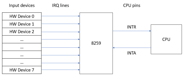
The 8259 can connect to up to 8 hardware devices as inputs, with each device connected to the 8259 via IRQ lines. This means it can relay up to 8 IRQs to the CPU. It has one output, which connects to the CPU’s INTR pin, and an additional input that connects to the CPU’s INTA pin.
Note : The INTA pin is used to signal acknowledgement of an interrupt.
When the 8259 receives an IRQ from one of the devices, it relays the IRQ to the CPU’s INTR pin. The CPU acknowledges the IRQ via the INTA pin. Together with the 8259, it determines which of the 8 devices had sent the IRQ in order to invoke the relevant ISR.
In the case where multiple devices issue a request at the same time, the 8259 uses a priority encoding algorithm to determine which of the devices should be granted access to the INTR pin first.
The 8259 can also be cascaded with other 8259s to service more input devices (and hence relay more IRQs).
In some older systems, there would typically be two 8259s cascaded to service 15 input devices. One of the 8259s serves as the master, while the other serves as the slave. While the master 8259 interfaces with the CPU, the slave 8259 outputs to one of the master 8259’s input channels. This makes the slave one of the master’s input devices. The following diagram illustrates this setup :

When the slave receives an IRQ from one of its input devices, it relays the IRQ to the master. The master in turn relays the IRQ to the CPU.
There are, however, downsides to this arrangement. A single 8259 can only service up to 8 input devices. As a result, systems with more hardware devices would require multiple 8259s, leading to issues such as reduced motherboard space and increased cost of manufacture. Furthermore, the master 8259 can only interface with one CPU (and one INTR pin). The single INTR pin connected to the master cannot relay data to other CPUs, making the arrangement unsuitable for multi-processor or multi-core systems.
CPU-Triggered Hardware Interrupts.Note that other than interrupts invoked by external hardware devices like the keyboard, there is another category of hardware interrupts which are triggered by the CPU itself. An example is the “Divide by Zero” interrupt (INT 0 on 8086 CPUs).
These interrupts do not involve the INTR and INTA pins. They are triggered through the detection of certain conditions by the CPU. In the case of zero division, the Arithmetic Logic Unit (ALU) detects such an error and this causes the CPU to lookup the IVT for the ISR for INT 0. The ISR is thus executed. For more information on the zero division interrupt, see this stackoverflow post.
Another example of interrupts triggered by the CPU is the Overflow Interrupt which occurs in the event of an arithmetic overflow. The overflow flag is set in such a situation and the ISR for this interrupt (INT 4 on the 8086) is executed. See this article for more information on arithmetic overflows.
Software Interrupts.Software interrupts are interrupts which are triggered by assembly code instructions which are executed by the CPU. In other words, they originate from running programs.
Both hardware and software interrupts involve the use of the IVT and ISRs. The main difference lies in how the interrupts are invoked. We have seen that hardware interrupts are invoked through hardware requests for CPU attention, the INTR pin being the entry-point of action. Software interrupts on the other hand are triggered through a running program, i.e. through assembly language code. They are a form of request for a service from the OS or the CPU. An example from the old days of MS-DOS is a request to print a character on the screen.
In assembly language, the INT instruction is used to issue a software interrupt. The format of a software interrupt is INT x, where x is the type number.
Note : Hardware interrupts can be simulated and tested via software interrupts. For example, the “Divide by Zero” interrupt can be tested by writing the instruction INT 0 in code. This will cause the CPU to lookup the interrupt’s IVT entry and execute the relevant ISR, much like what will happen if the interrupt was invoked by the CPU instead.
BIOS and DOS Software Interrupts.When exploring software interrupts, we will use the MS-DOS OS as an example. We will also look into software interrupts supplied by the system BIOS (Basic Input-Output System).
Both DOS and BIOS interrupts provide services for interacting with I/O devices. However DOS also provides other operating system services like file and disk directory management. Note also that a specific ISR (linked to an interrupt number) may provide more than one functionality. The specific functionality is selected by setting specific values into registers. An example is given below.
For instance, take the DOS interrupt INT 21h. INT 21h can be used to perform different actions based on the values contained in associated registers. One example is INT 21h / AH = 1 (or INT 21h with the value 1 passed into the AH register). This will perform the action to read in an input character via the keyboard. Another example, INT 21h / AH = 2, is used to output a character to the console. This variant also involves the DL register which stores the character value to be output. In this sense, the registers associated with INT 21h serve as parameter holders.
A difference between BIOS and DOS interrupts is that BIOS ISRs are more low-level and closer to the hardware than DOS ISRs. In fact, some DOS ISRs do make use of BIOS ISRs to access peripheral devices.
BIOS Interrupts.BIOS interrupts, aka ROM BIOS, are located in ROM (Read-Only Memory). When the PC is booted up, the the routines in the ROM BIOS are copied to RAM, and IVT is filled with the appropriate addresses of the BIOS routines. This is also known as shadow memory. Shadow memory is write-protected in order to protect the BIOS routines from being altered.
This is similar in concept to : programs are stored in the hard disk, but when they begin running, their contents are loaded into RAM.
When the CPU intends to communicate with an I/O device, it invokes the relevant BIOS ISR. This usually involves sending an output to an I/O port, from which the I/O device reads. From there, the I/O device performs the intended action.
An example of a BIOS interrupt is INT 10h, which pertains to the video display. INT 10h provides various functionalities specified by parameter values loaded into the AH register. Furthermore, depending on the required functionality, other parameters may be required. If so, these are stored in other registers.
One functionality of INT 10h is INT 10h / AH = 0. This interrupt is for setting the video mode of the system to either text (only ASCII characters can be displayed) or graphical (any bitmap image can be displayed).
INT 10h / AH = 0 also involves the AL register. The video mode is set based on the value passed into the AL register :
- 00h : Text mode 40×25 is set. This means that, at maximum, 40 characters can be displayed per line for a maximum of 25 lines of text.
- 03h : Text mode 80×25 is set. This means that, at maximum, 80 characters can be displayed per line for a maximum of 25 lines of text.
- 13h : Graphical mode is set.
INT 10h / AH = 0 will be demonstrated in a code example later in the article.
DOS Interrupts.DOS interrupts are supplied by the MS-DOS OS. As mentioned earlier, DOS interrupts provides a wide variety of functionalities, from servicing I/O devices to services like file and disk directory management as well as information on the system date and time. DOS interrupts are accessed via INT 21h.
An example DOS interrupt, INT 21h / AH = 2, will be demonstrated in a code example later in the article.
Code Example I – BIOS & DOS Software Interrupts.For this code demo, in order to demonstrate BIOS and DOS interrupts, we will be using DOSBox to emulate the DOS environment. Note that the Windows command prompt is not MS-DOS. See the following link for more information.
Also, note that modern compilers of today (e.g. Visual Studio) are not able to create MS-DOS programs. Hence we need to use an old compiler like Turbo C++ IDE to create DOS programs.
Some Background Info on DOSBox and Turbo C++.This video serves as a useful guide on how to install and setup these software. In case the Turbo C++ download link in the video description is no longer available, here is an alternative download link.
For the benefit of the reader, the following screenshots show DOSBox and Turbo C++ running within a DOSBox window :

The DOSBox window.
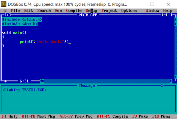
The Turbo C++ window.
Note that programs created by Turbo C++ will not be able to run in Windows 10. The following screenshot shows this :

We will now examine a C++ program, written in Turbo C++, which demonstrates BIOS and MS-DOS software interrupts. The source codes of the program can be downloaded from here.
It is important to note that the program is a DOS program. Hence it can only run in DOSBox and cannot be run in the Windows command line.
#include <stdio.h> #include <dos.h> void display_string() { asm mov ah, 02h asm mov dl, 'a' asm int 21h asm mov dl, 'b' asm int 21h asm mov dl, 'c' asm int 21h } void set_video_mode(int mode) { asm mov ah, 00h if (mode == 0) { asm mov al, 00h } else { asm mov al, 03h } asm int 10h } void main() { set_video_mode(1); display_string(); } set_video_mode()The set_video_mode() function demonstrates the BIOS interrupt INT 10h / AH = 0. It takes in an int variable which determines which text mode should be activated. If the parameter value is 0, 00h is passed into AL, setting 40×25 text mode; otherwise, 03h is passed into AL, setting 80×25 text mode.
set_video_mode() does not demonstrate the graphical mode.
display_string()display_string() demonstrates the DOS interrupt INT 21h / AH = 2.
The interrupt is invoked three times in the function. Each time the interrupt is invoked, a different character value is placed into the DL register. The ‘a’ character is used for the first invocation, then ‘b’ for the second invocation, and finally ‘c’ for the last invocation. The character string “abc” will hence be displayed on the console.
Note : INT 21h / AH = 2 only works for hard-coded character values. It does not work for character variables. The following, for instance, will not work :
void display_string(char c) { asm mov ah, 02h asm mov dl, c asm int 21h }The following are screenshots of sample runs of the program :

In the above screenshot, the value 0 is passed into set_video_mode(), which sets the text mode to 40×25.
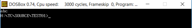
In this other screenshot, the value 1 is passed into set_video_mode(), which sets the text mode to 80×25. display_string() is unaffected in either case.
Code Example II – Software Interrupts in Windows.In this final section, we will demonstrate how software interrupts can be invoked in Windows. In particular, we will look into the different ways in which INT 3 (the breakpoint interrupt) can be invoked in code.
The source codes of the program can be downloaded from here.
Configuring the Postmortem Debugger.Before running the program, you may need to change some settings in your PC’s registry in order to configure the postmortem debugger. When INT 3 is executed in code, the ISR for this interrupt will be invoked as expected. For the Windows OS, this ISR will launch a pre-registered debugger.
The debugger has the potential to allow the user to view system internals at the point where the INT 3 occurs. We will see this in the code demonstration later on.
Back to the registry settings. Open the Registry Editor and navigate to the AeDebug registry key. Note that there are 2 such AeDebug keys (one for 32-bit programs and the other for 64-bit programs). The registry paths are :
32-bit : HKEY_LOCAL_MACHINE\SOFTWARE\WOW6432Node\Microsoft\Windows NT\CurrentVersion\AeDebug\ 64-bit : HKEY_LOCAL_MACHINE\SOFTWARE\Microsoft\Windows NT\CurrentVersion\AeDebug\In both AeDebug keys, a string value with the name “Auto” must exist and set to value 1. If this string value does not already exist on the reader’s registry, create it.
Below is a screenshot of the registry editor, showing the “Auto” value in the 32-bit AeDebug key :

The Auto = 1 setting will cause the activation of the debugger when a program executes INT 3. If Auto is set to 0, or if there is no Auto value, the interrupt will instead cause the program to crash.
Refer to the following articles for more information : 1 2. For article 2, focus on the section “Configuring Automatic Debugging for Application Crashes”.
Program code. #include <windows.h> void DemoDebugBreak01() { DebugBreak(); } void DemoDebugBreak02() { __debugbreak(); } void DemoDebugBreak03() { __asm { int 0x03 } } void main() { DemoDebugBreak01(); }Each of the program’s functions demonstrates a different way to issue INT 3 in code.
The first function, DemoDebugBreak01(), calls the DebugBreak() function. DebugBreak() is the Windows API for invoking INT 3.
The second function, DemoDebugBreak02(), makes use of an intrinsic function to invoke INT 3. What this means is that there is no actual function call; instead, the code for invoking INT 3 is embedded in the DemoDebugBreak02() function itself. For more information on intrinsic functions, refer to this stackoverflow post.
The third and final function, DemoDebugBreak03(), directly embeds the assembly code for invoking INT 3 in the function.
Running the Program.Note that my sample program is a console program. Hence it must be run in a command prompt. Immediately after it starts, the following window will appear :
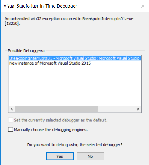
Due to the invocation of INT 3 in code, the debugger will be launched by the OS. In my system, Visual Studio has been set as the debugger, hence the above dialog box will be launched. Select “New instance” and click Yes.
Note that if the following window appears instead :

This means that a postmortem debugger has not been configured to run. Refer back to the section “Configuring the Postmortem Debugger” for more information.
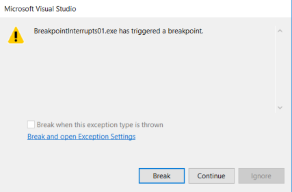
When Visual Studio continues, the following window will appear. Select “Break”.
In this sample run, DemoDebugBreak01() is called. As you can see in the screenshot below, DemoDebugBreak01() makes a function call to the DebugBreak().

Stepping into the function call, you will see that INT 3 is indeed called in the DebugBreak() function :

If DemoDebugBreak02() is called, the following is shown instead :

Instead of a function call, INT 3 is copied to and embedded in DemoDebugBreak02(). This shows an intrinsic function in action.
Lastly, if DemoDebugBreak03() is called, the following is shown :
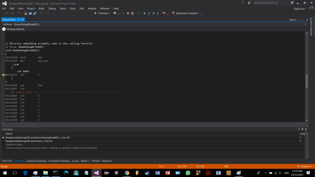
Regardless of the function called, the program will eventually reach INT 3.
Some Notes Regarding INT 3.One of the best ways to use INT 3 is in error checking. For instance, if the program is buggy but the cause of the error is unknown, an INT 3 can be issued at the location where the error occurs. The program can be left to run as per normal until it reaches the “error point”, at which INT 3 is invoked, allowing the developer to view the system internals such as the call stack, memory, and registers. This helps the developer to trace the error, root out the cause, and resolve the issues.
Summary.In this blog, we have examined hardware and software interrupts. Recall the following :
- The only difference between them is in the way the interrupt is triggered. The common thing between them is the IVT and the ISRs that services interrupts.
- Some hardware interrupts, such as the “Divide by Zero” interrupt, are triggered by the CPU itself instead of external hardware components.
- The breakpoint interrupt, INT 3, can be very useful for investigating bugs. It is not always practical to run programs under the debugger, especially for large programs; using INT 3, the program can run normally up to the point of error, at which the interrupt is invoked, allowing the developer to view the system internals to help resolve the bugs.
I hope that you have enjoyed reading this article, and that you are now inspired to learn more about interrupts and how they work. I certainly found it interesting to research this subject and learn about the various types of interrupts, how they are triggered, and how they can be invoked in code.
References.The x86 Microprocessors: 8086 to Pentium, Multicores, Atom and the 8051 Microcontroller, 2/e: Programming and Interfacing – Chapter 8, The Interrupt Structure of 8086
What is the Difference between Hardware and Software Interrupts?
Instruction Cycle
What is the purpose of CS and IP Registers in Intel 8086 Assembly?
Operating System #14 What is an Interrupt? Types of Interrupts
Interrupt
Intel 8259
Operating System #16 Software Interrupts | System calls in xv6
Non-Maskable Interrupt
Run Turbo C Compiler in Windows 7 and Vista using DOSBox
8086 Interrupts
Enabling Postmortem Debugging
Configuring Automatic Debugging
Advanced Programmable Interrupt Controller – Useful information on the APIC, another type of interrupt controller.
Microprocessor – 8086 Pin Configuration – A useful guide to the pins of the Intel 8086 microprocessor.
Microprocessor – 8086 Interrupts – A useful guide to interrupts in the Intel 8086 microprocessor.
Advertisements Share this: