Sync and Word Clock
Fig. 1 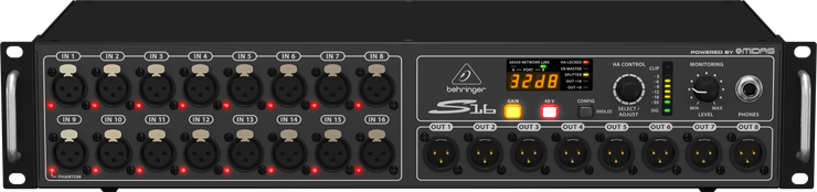
When we talk about digital audio we will see in more detail the importance of a correct and stable Word Clock, for the moment let’s just understand its importance in connecting digital audio equipment.
Each digital connection has a generally green LED (as seen in Figure 1, defined as A and B for connecting the AES50 protocol but may also have different names based on the protocol used and the number of manageable connections), Illuminated LED identifies that the signal is present and synchronized and the system works, if it flashes or in some cases is red means the system detects the signal but is not synchronized and therefore the signal does not circulate.. If it is off it means there is no signal connected to its input (in Figure 1 as you see the B is on and fixed then the signal is there and it is synchronized, while A is off so there is no signal to its input).
n.b. Different Digital Stage Box may have different LED notifications sometimes even graphics, depends on the manufacturer and the quality of the same Stage Box, which is essential therefore to know the characteristics of the used product.
We will see in more detail in other arguments the structure of the digital signal and its operation.
In summary, a digital signal contains in itself sampling information, quantization and the structure of the protocol used to transfer this signal from an output device to an input, it will be necessary for the input to have a device for translating and eventually transferring to other inputs this signal so that it can be processed and transmitted, among the many parameters that these devices have to have is the Word Clock that represents a data stream that accompanies the digital signal (anticipating it) with the task of telling the device of input as you have to behave to read the digital signal information that is coming. Generally is used to manage the sampling frequency, for example, if the digital signal has a sampling frequency of 96 Khz the world clock in anticipation of the signal will tell the input device that will be working at 96 Khz and also as it must do so, in most professional audio systems is the ability to choose whether to send the word clock from the output signal or receive it from the input signal for reasons and examples that we will see later (some input devices are in auto-setting on the frequency dictated by the Word Clock, others especially those who turn can generate a Word Clock are setup on the sampling frequency of the digital audio signal). There are different types of World Clock some more precise and quality than others.
The signal sending clock is defined Master while the one receiving the slave. The Master Clock must and can be 1 while the Slave can be more than one as more digital devices may need to be synchronized.
n.b. If I put in Master Clock both the output device that input obviously the system will not work, the same for the slave.
Some digital audio mixers have an external interface (figure 2) to allow the use of external Word Clock generators (fig. 3), sometimes more qualitative and precise than those contained within the equipment such as digital audio mixer and Stage Box. In this case the audio mixer will then have to be set for picking up the word clock from the external generator.
Fig. 2 
In figure 2, the IN is where it will be connected to the output of the clock generator, while from OUT be possible to withdraw the same clock be sent also to other digital devices that accept external clock.
Fig. 3 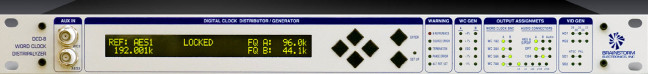
If you use a digital audio mixer connected to a digital stage box, generally especially at the professional level you can decide whether to use the word clock of the audio mixer or take it from the Stage Box (as a professional level all Stage Digital Box can generate their own Word Clock).
In this case the best solution is always to give the Word Clock from poorer device (so as to be able to define its own pace, so that all other devices follow his, otherwise it would risk “bottlenecks” and the malfunctioning of the system), or from the device in which the first to exit the digital audio signal (more qualitative because the more rapid and lower latencies generator, but if the input device is poorer then not able to follow the trend of the Clock is likely precisely “bottlenecks”). Generally, the digital audio mixer is that must handle most of the clock between inputs and outputs of the various present connections, plug in, graphical user interface, for which there is a tendency to put as Master (then generator Word Clock) the digital audio mixer (fig. 4). The Stage Box automatically (if set in the same sampling frequency of the digital audio mixer) will become slaves (then wait for the clock from the audio mixer before withdrawing and circulate the digital audio signal).
Fig. 4 
n.b. Remember that any digital audio device must be set at the same sampling rate to function.
If we set instead of receiving the Clock from the Stage Box in the audio mixer settings, the audio mixer will become slaves and Stage Box Master, some Stage Box have a generally red LED (called Master), which when illuminated identifies the signal is present and the device is a Master Clock generator.
If we use more Stage Box with Daesy Chain configuration or Stella, the digital audio mixer must always be set as the master (fig. 5), this makes the system more stable being able to reduce the occurrence of errors by the passage of signal from input devices and output between the various Stage Box, as well as be able to receive and then manage independently of the Box Stage signals.
Fig. 5 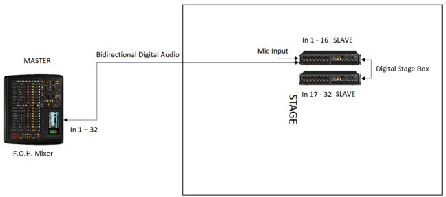
In some cases, more often Digital Stage Boxes, especially for Daesy Chain configurations, if I place as Master Clock one of the Stage Boxes and the rest in Slave it is possible to distribute and use only the Stage Box Master signal (figure 6 ), as the Stage Box Master would be the one that sends the digital signal including protocol and word clock that passes through all the other Slave Stage Boxes to the audio mixer, whereas as seen, you have to have the audio mixer like Master clock so it can receive signals from all Stage Box independently.
Fig. 6 
As can be seen from Figure 6 the first Stage Box is set as the master and is configured for the management of the input channels 1-16, while the second Stage Box is set as a slave and set for the management of the input channels from 17 to 32, the outputs will be set and can be configured accordingly by the digital audio mixer, which in turn is set as a slave, in this case as said digital audio mixer would arrive only channels 1-16 of the Stage Box Master.
If you have a digital stage and stage mixer configuration you will need to consider it as one of the two master mixers (usually the one closest to the Stage Box so it can travel the Clock signal short path as possible) and the rest Slave (figure 7).
Fig. 7 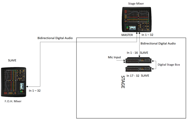
In the presence of additional Stage Box and digital audio mixers these shall always be slaves, both a configuration in Daesy Chain as in the examples that for a configuration in Stella.
When an audio device (example audio mixer or rack matrix) has a specific clock signal output (figure 8), this is useful, for example, to send a clock reference to devices connected to the same line as seen before necessary and useful if the master and/or receiver clock of equipment has problems and / or has no stability, or especially when using SRC or ASRC to handle different equipment that work on different paths and/or different sampling values as we will see now.
Fig. 8 
If, for example, I have two devices that dial with a different sampling value, you will need to interpose a SRC or ASRC converter (we will see these devices in more detail when we talk about digital audio), taking the sampled signal from the Master and sending it to the converter this will transform it into a sampling level appropriate to the Slave or Spare device receiving it. In this case, it is more appropriate to use a sampling converter that can receive the clock from the Slave device so that it can handle clock times and then sampling according to the Slave or Spare device. Thus, if the Slave or Spare device has problems in maintaining the clock’s stability, it will tell the converter to act accordingly with the given rhythm. This guarantees greater security in the transfer of clock and therefore sampled signal than the simple passage of the signal from the master to the converter and then pick up the converted signal to be sent to the Slave or Spare device, since if the device has exactly said problems of stability would tend to create bottle holes and sampling errors (jitter) until the signal stops working (figure 9).
Fig. 9 
n.b. From the converter settings SRC or ASRC, you determine the output sampling level (some also need to determine the input level, so they are not automatic in the detection).
Another example, if I have two or more devices on separate lines that can in turn have the same or different sampling (if different, you will need to use an SRC or ASRC) and manage the clock from an external rack unit like the one in figure 3 (its use is fundamental since as seen earlier if the audio line clock is used on a Slave device and this clock also fails, the Slave or Spare equipment stops working, while having an external clock it continues to go, obviously unless the external clock generator is interrupted), (see figure 10A) (we’ll see later on how to create signal paths and increase the redundancy levels ).
If the devices are with a level 3 redundancy (we will see more detail about redundancy when we talk about digital audio), if the external unit clock jumps, the redundant devices automatically move to the value of their internal clock that could also be different from the one dictated earlier by the external rack clock, and also different between one device and another (the passage is always random based on where the redundancy system of the device sees a clean and stable signal), and become both masters clock (basically the system gets clock generator) by creating signal interruption for the Slave or Spare device in conflict with the other device in turn Master.
To avoid this problem, a configuration type is used as in figure 10B.
Fig. 10 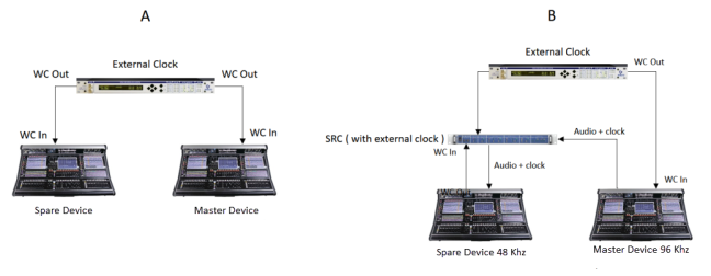
Figure 10A shows the configuration of the signal path with the use of an external clock generator in which outputs are generally sent to the BNC connector the clocks for the two devices to be controlled, in this case a master and a spare. Depending on the capabilities of the clock interface, there may be a possibility to send a single clock type or different output. The two devices will then have to be configured to receive external clock.
To avoid system interruption in case of external clock generator failure, as mentioned above, a configuration is used as shown in FIG. 10B, wherein (assuming in each case a different sampling value between the two devices, one at 48 Khz, the other at 96 hz, but as mentioned also for a redundancy problem in which both devices would take master clock), it connects the external clock generator with a clock line to the master device and a clock line to SRC converter, to which the converter reaches the clock defined by the spare device, and at the input of the SRC comes the already provided clock signal of the clock (on a protocol dependent on that of the interface used by the master device itself) sent by the master device. at the input of the spare device comes the audio signal choked by the SRC converter.
For complex and articulated systems that use splitter, in this digital case, use a configuration similar to figure 11.
Fig. 11 
For which, the audio clocked by the master device that is no longer arrives at the SRC converter but on the Splitter, which then provides one or more branches to external devices, which in turn comes from the clock from the external clock generator (if it no longer has outputs there are split splice arrays for the clock or devices that can be connected to the bridge to handle the system with a single system with multiple outputs/inputs). One of split splits is sent to the SRC converter. The rest of the connections is the same as shown in figure 10 B.
Conclusions
Whatever the configuration, if we are in the digital domain so with the use of digital audio mixer, these mixers will be pre-configured in order to be able to communicate and transmit the audio signal to and from the Digital Stage Box – Splitter, also the same Digital Stage Box – Splitter if more than one will have to be configured (on board and/or through external software) to communicate with the digital audio mixer and to each other. It is therefore necessary to perfectly know the characteristics of the material used.
It must be said also that some digital audio mixers, especially non-high-end, do not allow all customizations seen, make it impossible to choose independent IN/OUT routing for each channel but work as a group, sometimes limited by the protocol used
Currently they are coming on the market also some wi-fi systems, both for dialogue between digital audio mixer and digital stage box both for the dialogue between the output lines that input through radio transmitters and receivers, but we are still technologically backward, especially in terms of quality and reliability.
Even the same Port Switch (fig. 12) seen in the topic Stage Box but also in Splitter and Adders can be considered Splitter and Adders as it is possible directing the digital audio signal to both network cable but also fiber optic for devices that allow it to any direction via an internal and / or external software interface.
Fig. 12 
We will see in future arguments the structure and function of each digital protocol used in professional audio environment with other configuration examples of both graphics and videos.
n.b It is important that the switch-router is of high quality, as poor devices may hurt the audio signal with errors, causing bottlenecks and network jitter phenomena.
Constructive Design of Audio Splitters
As mentioned in this set of articles, each constructor can have its own configuration of creating a splitter (from form and size to audio signal management type), whether analog or digital, but the operating principle is the same.
Below are some splitter representations in constructive configuration different to the one analyzed so far:
Fig. 13

In figure 13, a single-rack unit passive splitter with XLR microphone inputs on the front and split outputs on the back, with the possibility of lifting the bulk and handling the phantom power.
Fig. 14 
In figure 14, a passive analog splitter with Jack TRS inputs and outputs in the back of the rack (where it is also possible to extract from the set of all the input signals mixed out from the controls in the front panel, from expand out the ability to bridge more splitters to create one with multiple input and output channels, and from master in the ability to send a left and right master mix to split at various outputs).
Fig. 15 
Others such as this in figure 15 also provide a control to balance the signal level at split outputs (useful for example in fixed installations and without the presence of a control matrix for input and output levels). This splitter uses a pan control to control which split outputs send the signal, if in the center position the signal is sent to all outputs, all right only to the first one, all left to the last one and etc.
Others still have the option of choosing the type of signal to be received (- 10 dBV, 0 dBu, + 4 dBu).
Fig. 16 
In figure 16, an active splitter with inputs in the back and out in the front, with the possibility of detecting whether the input is a microphone or inserting the 10Kohm resistance and making it as a line input, as seen in Figure 16 then presents a control of the gain of the screw audio signal level, which is why the use of a cutting screwdriver for its modifications (useful against impacts and accidental manipulation and unauthorized personnel).
Fig. 17 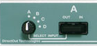
Some models like the one in figure 17 have a selector to decide to which split output to send the signal.
Fig. 18 

Some such as those in figure 18 also provide inputs and/or outputs on DSUB and/or Euroblock.
Fig. 19 

Other construction designs may include portable shapes similar to D.I. Boxes like these in figure 19.
Fig. 20 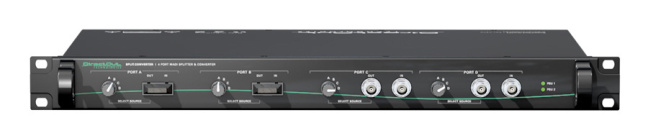 In figure 20 a digital splitter with splitter output selector, this splitter accepts signals on MADI fiber optic protocol and BNC.
There may be splitters for different protocols and mixed protocols.
Fig. 21 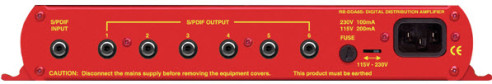
In figure 21, a digital splitter with inputs and outputs S / Pdif, but can also be found for AES3 and mixed lines.
As you can see, each manufacturer can expect different features and control of the audio signal to be split.
The same analog Patchbay (figure 22) or even more digital (figure 23) can be considered splitter. With analogs, you can usually split one input for each input, while in digital you can copy an input signal to all audio outputs (then have 32 to 64 outputs for an input signal as well).
Fig. 22 
Fig. 23 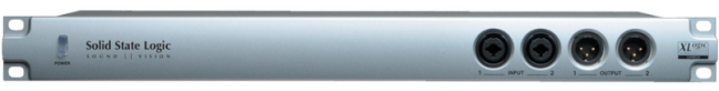
Adders
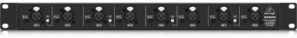
An Adder or Matrix Mixer or Zone Mixer sometimes called even Summing Amplifier as it has pre-amplifiers in the input stages if it provides mic and line inputs, otherwise it would be a common splitter, it’s the simplification of an audio mixer with the only purpose of mixing one or more input signals to be sent to one or more outputs, in practice it’s the opposite of the splitter and is generally on the rack (fig. 24).
Fig. 24 
They are generally in the form of racks, so that they can be installed in racks and are easily portable because of the small size and the weight that is not excessive.
That’s why they are very used and ready for use in commercial installations (bars, restaurants, shopping malls, shops, conference rooms) (especially the Zone Mixers that we will see have many more control options than a simple adder).
The adder can be Passive (almost never used) or Active (almost always as more qualitative but more expensive) which need for external power supply.
Those passives are poorer and therefore little used, generate noise and distortion on the output signal especially for those hand-wired, while those in transformer generally have a slightly higher quality but they are also much more expensive given the quality of transformers required for get a quality sound (as seen for Splitter).
Those assets are the most widely used:
The following is a hypothetical Active Adder circuit (fig. 25 by ilprogettista.it).
Fig. 25 
n.b. The resistances of the input channels in the example in Figure 9 represent any fader or rotary controls in the management of the input signal to send the desired amount to the outputs.
There are not at least professional-level digital subscribers (except for internal DSP processing) since already the Stage Box – Digital Splitters, digital audio mixers allow as you see the most varied configurations with the highest and most necessary audio output numbers available for cover any kind of event (as seen also in previous articles on Stage Boxes and Digital Splitters). We will see, however, there are Zone and Matrix mixers with constructive digital variants compared to common concert audio or recording studios.
It looks for example like in figure 26 where you see the part Front in which it is possible to generally adjust the Pan for left – right (if stereo) or more if it provides multiple independent outputs, so as to decide to which output you want to send the relative input signal, and the amount of signal to be sent to the output through a rotary potentiometer with the same function as an audio mixer fader, which gain is generally from – ∞ to + 0 dB, + 10 dB, +12 dB, + 15 dB. It also has a Master control of the general level of the outputs which has always the same parameters of the controls of the individual input channels.
Fig. 26 
In the Back, however, there are almost always input connectors on the XLR or Combo as shown in Figure 26, but sometimes also on a D-Sub connection as in Figure 28, the number of inputs that can be carried by a single adder module is not fixed, they can find 2-channel, as well as 8-channel, 16-channel, and so on, always with rack sizes.
Always in Back are also the output connections (generally called Master Out or Main Out or Mix Out) almost always on XLR (fig. 10) or D-Sub (fig. 12), you can find a Master Out or more ( if more, each Master Out will be appointed with a number, such as Master Out 1, Master Out 2 etc … or with a letter, Master Out A, Master Out B, etc ..), one can find active outputs and / or passive so as to be able to determine the best output according to the noise present and / or generated along the circuit, the active output is generally always to 50 Ω (useful for sending the signal to the input of modern equipment with input at + 4 dBu), while the passive can also be 600 Ω (useful for sending the signal to the input of older equipment or consumer with 0 dBu input).
When there are multiple outputs, such as Master 1 and Master 2 as in the example in figure 10 and as a Pan controls you have only the Left and Right means that the input signal comes out as a copy to all and two outputs with the only possibility of send the signal to the Left or Right of both outputs, useful when it is necessary to split the summed signal on more than one output, as one toward the PA L-R (audio system) close to the stage, and one toward a Delay Tower torque for the sound of large listening areas (we will see in future arguments types of audio equipment and their installation).
The adder is constructed exclusively for accepting signals at the level of line 0,775 v – 1,223 v with input impedance of about 10 KOhm or 20 KOhm, to be sent to one or more outputs to the power amplifiers input or audio speakers amplified to increase the number of sound diffusion points without using the link of the power amplifiers signals and amplifiers themselves especially for large sections and with large number of power amplifiers or active audio speakers, which in addition to having to use meters and meters of balanced cable in more lead to a greater increase of the background noise and distortion due to the many links that are executed and especially if these have an amplification circuit on the input signal and then produce fluctuations) in the audio signal, always background noise and reduction of dynamic range.
Some of the more professional Suppliers, like the one in figure 27, also have the CUE or SOLO for headphone pre-listening.
Fig. 27 
Fig. 28 
There may also be a possibility of interfacing the device with a computer for remote control through a D-SUB connection as seen in figure 26 or via USB as shown in figure 28.
Some Inputs such as in figure 26 do not have meters for Input and Output Signal Controls, this saves space especially if built up with many input channels and allows it to be built on racks, others instead as in figure 27 present VU Meter (especially if there are valves for signal level control) or Peak Meter (if purely made with amplifiers and resistors). The control will have to be done by the meter, which controls the level of the output signal that arrives at the input of the summer (the meter of the audio mixer) and the input signal meter, for example the power amp in which the signal arrives in output from the adder.
In the example in figure 28, some of the Adders may have the Mass Removal Selector in case of disturbances along the signal lines, they may also have insert in / out connections to insert any frequency and / or dynamic processors on the input signals.
Always taking the Adders in figures 27 and 28 as examples, some use digital domain signal processing with converters having a sampling rate generally ranging from 44.1 kHz to 192 kHz, but inputs and outputs are always in analog domain including rotary potentiometers of the input circuit to control the signal level to be sent to the outputs.
High-level adders such as those in figure 27 and 28 can also be upgraded with external interfaces, such as a Fader pack (figure 29) for better and more accurate signal level control to be sent to outputs than rotary controls. Generally, they can be connected via USB (if digital) or D-Sub (if analog) connection.
Fig. 29 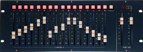
Generally, an Adder offers a maximum of 3 copies of outputs, this for the same reasons seen qualitative for active audio splitter in which over a number of split it begins to introduce a significant background noise and distortion.
The Adder generally also presents the Mute button in order to turn off each channel independently.
n.b. Generally an Adder is enough to cover even the largest, most complex configurations on the number of channels used for the output, because this is to be used along with the output of the audio mixer, the adder is considered to be added for additional outputs, never use it in replacement because as we will see that the output of the audio mixer should be sent to the input of the Adder who then has the task to split the signal into multiple outputs (unless you do not have line of independent signals that do not enter in the audio mixer but directly in the input of the adder to be summed with the rest of the input channels). It is therefore to use only if the audio mixer does not have such a number of outputs that you can cover all the locations in which you need to send an independent audio signal. This is because it is still a component in the longer the path of the audio signal that generates its own noise and its distortions.
Some adders include interchangeable modules (generally with pre-amplifiers of the same brand) (fig. 30).
Fig. 30 
If you already have the right amount of outputs on the mixer, always use those (fig. 31).
Fig. 31 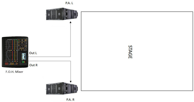
In the event that you have instead a pair L – R of Delay Tower for sonorize wide spaces and the audio mixer has for example only one usable output in addition to the L – R then it may be necessary to interpose an adder in order to increase the number of outputs manageable and also bring the signal to the two Delay Tower (fig. 32).
Fig. 32 
As can be seen from figure 32, this audio mixer has 3 outputs, a L, a R and a matrix, the L and R we use them to send signal to the PA while the Matrix we use it to send the signal to the adder which will put us to its output a pair of signals L – R, which will be sent one at Tower Delay L and the other to Delay Tower R.
The adder is always positioned close to the audio mixer station, this in order make travel the analog line signal from the mixer output the route possible (from the output of the mixer input of the Adder), although balanced, thus optimizing the quality of the signal.
Another configuration in order to connect the Delay Tower or in any case any other audio speaker more, to which having to send the audio signal would be to put in the various links power amplifiers or active speaker audio amplifiers, as in the example in figure 33 and 34.
Fig. 33 
Fig. 34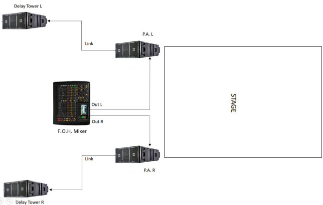
In figure 33 we see that there is the inability to manage volumes independently of the Delay Tower L and R as raising the volume of one also would raise the other, always having to act on the gain level of the final power amplifiers or if active speakers to compensate for the variation (impassable road and of lesser quality), plus the distance that the audio signal is longer than that traveled by using the adder, in fact, the audio signal in the figure 13 exits from the Matrix Out, arrives at the input example of the first final power of the Delay Tower L, from there take the link and sends it at the input of the second final power of the Delay Tower R, signal path that could also easily get to 100 and more meters. With the Adder, instead of the signal from the Matrix Out arrives at the input of Adder, he picks up a copy L to be sent to the first Delay Tower and a copy of R to be sent at the second Delay Tower, also drawn much shorter than half, and in the more, you have the ability to manage independently the volumes of the Delay Tower L and R.
For figure 34, the principle is the same except that the signal is in a link from the P.A., with the inability to manage independently from the P.A. from the Delay Tower.
n.b. We will see in future arguments the types and methods of installation of sound systems and the importance of being able to independently manage signals.
For commercial installations as seen before, mixer zones are more suitable for routing inputs and outputs, so that being in a rack format and without the need for a technician present all the time (not having to mix) you can store the mixer areas in the proper accommodation when wired (not to interfere with normal everyday work, not to disturb the image of the shop, mall or restaurant being, and being away and protected from dust and moisture).
And so, in this case they will replace the audio mixers used in the professional environment in live, studio, broadcast.
Features:
A great analog adder must have some characteristics of fundamental importance to be considered quality, including the highest input signal level bearable before generating no longer tolerable distortions which > + 20 dB, the minimum harmonic distortion value as the < 0.05 or < 0.02% THD, the lowest background noise about < 80 dB.
If it is digital and therefore it comes in the form of Splitter – Digital Stage Box, external control matrix as audio mixer or simple signal processor Zone or Matrix mixer its features are the same views for Digital Stage Boxes and Digital Splitters.
Conclusions
Also other parameters may be present depending on the quality of the Adder, is so useful and fundamental before purchase to know what the signal path from inputs to outputs, to assess whether it is necessary to purchase the adder in the event that you do not has a sufficient quantity of outputs or you have a sound system arrangement such as to allow a greater quality of the audio signal if the present Adder as seen in the examples, and then study the operating instructions of each component of the adder so as to be able to buy the most appropriate one to suit you.
The same Analog or even Digital Patchbay can be considered as adder.
Any Splitter – Digital Stage Box but also analog or digital audio mixer is to be considered a summation.
Other types of Adders
Some new generation adders allow of interfacing in the input numerous types of digital and analog audio and sum to one or more outputs in analog or digital domain, it’s propose on the market as a direct alternative “compact” to the real audio mixer and own as we will see in other arguments.
Fig. 35 
Fig 36 
In figure 35 and 36 one Switcher – Adder capable of accepting input unbalanced signal on Jack 1/4″or 3.5 mm and propose to the output a balanced line, unbalanced and headphones.
Fig. 37 
In figure 37 an Adder capable of accepting in input digital signal via MIDI and USB or analog unbalanced, and provide the output analog audio signal balanced and unbalanced for a routing structure like the one in figure 38 (from Radial Engineering).
Fig. 38 
Fig. 39 
In figure 39, another type of adder also has a minimum of shelving equalizer (low-high) as well as an equalizer section and a usb connection for remote control (in this case it is more like an audio interface than to an audio mixer), for a routing like the one in figure 40 (from radial engineering).
Fig. 40 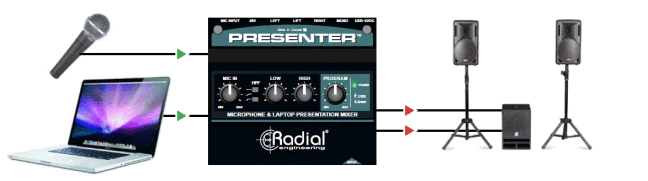
Zone – Matrix Mixer
Other, especially the Zone Mixer (fig. 41), which as previously mentioned, due to the characteristics, are more predisposed for commercial installations, have multiple functionalities such as consumer inputs (- 10 dBV), mp3 player, sd, internal hard disk, fm radio and digital radio, power output for constant voltage loudspeakers and / or constant impedance (fig. 42), and the most varied accessories.
Fig. 41 
Fig. 42 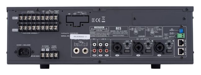
They can also possess Euroblock outputs (fig.43), remote control options, dynamic processors and frequency included (some are controllable and can be set by external software with which patch controls can also be used to handle routing of inputs and outputs).
Fig. 43 
Still others (the most advanced) and thanks to the evolution of the digital standard as we will see in other arguments (AVB protocol and AES67), provide for the transport of both audio and video from a single interface, more controllable using but also application software for mobile devices. So present digital outputs for the distribution of audio-video signals in a network (ethernet cable and / or fiber optic), often accompanied by the usual analog cable (generally on Euroblock or D-Sub), ( fig. 44 ).
Fig. 44 
Further matrices as well as analog or analog-digital mixed can have a full digital interface, such as Adders can be modular (fig. 45-46), have functions of intercomm and alarms and integration on a network for network management and remote control from a single access point, the higher performance also possess a dual power supply redundancy which intervenes when the primary stops working so as to maintain stable and active throughout the system.
Fig. 45 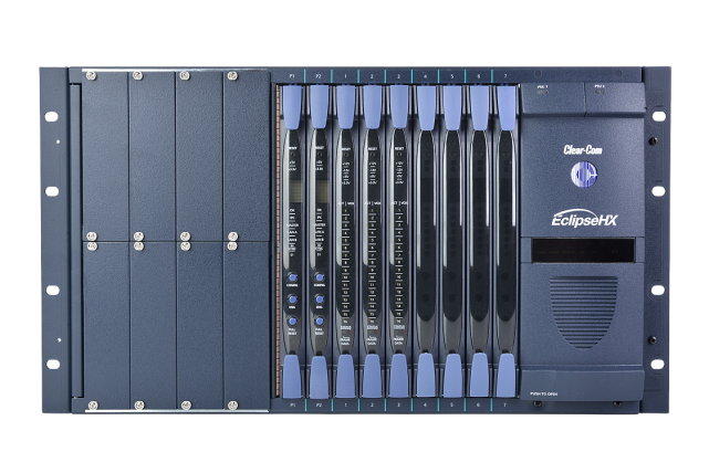
Fig. 46 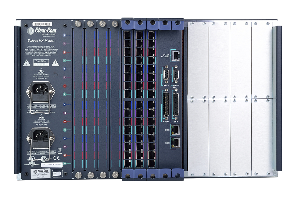
There are some that have DSPs deployed for complex routing management (in addition to equalization, dynamics, delay, anti-feedback), always through software and have convolutional processing capabilities (FIR – IIR), (which we will discuss when we talk of digital audio) and AutoMixer functionality (we’ll see when we talk about Audio Mixer), which can be connected remotely via Ethernet or RS485 for PC configurations, and also Wi-Fi for Smartphone and Tablet control, as well as having a remote connection for integration with other devices (for example, an external physical extension or extension matrix, then hardware and non-software). I can also present GPIO ports for the creation and management of complex systems (we will also see this when we talk about digital audio), like the one in figure 47.
Fig. 47 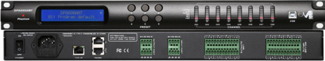
Any Splitter – Digital Stage Box, control matrices as digital audio mixers can have functions (as seen) and therefore be considered digital adders.
In figure 48, a matrix with multicore connections.
Fig. 48 
In figure. 49, a modular array for various types of digital interfaces and with complete integrated DSP control and In/Out management through software.
Fig. 49 
Nowadays they can also be controlled via WiFi via smartphones, PCs and tablets.
Other on Splitters and Summings:
Splitters and Summings – I ( Splitter Types, Analog Passive Splitters and their usage )
Splitters and Summings – II ( Active Analog Splitters and their uses, Digital Splitters )
Splitters and Summings – III ( Using Digital Splitters )
Advertisements Share this: