I have written about the Timed LED Lighting Controller in previous posts. Starting with the original entry “Stairwell Foot Lighting System”. In this entry I will be wrapping up the project and describing the change of direction from the initial design and layout. There may be a bit of overlap but it will be minimal as the project took a small deviation along the way.
Just to recap, the objective of this Timed LED Lighting Controller is to replace a stairwell foot lighting controller that was installed back in 2010. The former controller was a collection of discrete modules to take the signal from a PIR motion detection module and close a relay for a predetermined length of time. This relay would then drive a high power LED driver. There are three “zones” so this set up was repeated three times. At the time, I already thought it would be neat to replace this with a single microcontroller based system.
It was the motivation for this project that actual lead me to Contextual Electronics where I learnt to undertake such a project from inception to installation.
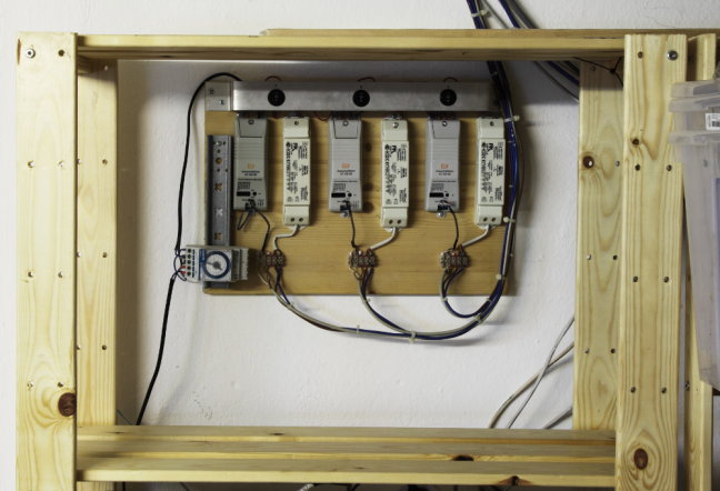 The Old Controller 3 PIR timers and LED driver for each zone
Related Posts
The Old Controller 3 PIR timers and LED driver for each zone
Related Posts
I have been chipping away on this project for about a year. During this time I have been documenting the approach and results as I go.
- Stairwell Foot Lighting System
- Timed LED Lighting Control – Design
- “Mocking” – Minimising Risk
- Back to Blinky
- From Proof of Concept to Prototype
Design Changes
As I was bringing this project close to the point of “mounting on the wall”, I started to have concerns. I.e. How could I reasonably install this so it would look better than what I already had? This sent me down a rabbit hole in researching enclosures. This lead me to consider “Hat” or DIN rail compatible enclosures. This also had a knock-on effect to bring the device into the new housing.
Schematic and LayoutI decided to still keep the 240VAC board separate from the control board. To fit this into the DIN enclosure, I made this two levels, one above the other. The larger board, in the base would be for the 240VAC components and the upper, would be for the control logic. This meant a rearrangement of the schematic. The smaller, upper control board holds the 12V and 3.3V LDOs, microcontroller and the connection to the Raspberry PI. The lower 240VAC board contains the relays, their interface and the connectors to those components that lay outside of the enclosure i.e. the PIR motion detectors. To create a robust connection to the Raspberry PI I opted to try out a RJ45 connector. This had the advantage of having enough lines for I²C and an interrupt as well as being easy to get, cheap and quite a solid connection. The downside of course, is that it looks like an Ethernet connection!

The decision to go with the DIN compatible enclosure also meant I had to rework the layout. The only way out was to simply order the enclosures and terminals to get them in hand to verify the measurements.

 Prototyping the board sizes
To make sure things lined up, the measurement function in KiCad proved to be very helpful. I modelled both boards in the one document. With the enclosures on hand, I could use the technique I have written about before – print out the boards and glue them to cardboard and just see how things will fit. Before sending the boards off for Fabrication, I copied this file twice and respectively removed the 240VAC board and the control board and submitted two separate orders to OSH Park. I could not panellise these boards as I had the control board as 4-layer and the 240V board as 2-Layer.
Assembly The boards fitted perfectly in the enclosure. Though I did have a doubt about the modelling of the pin header between the two boards and found some 2.54mm board spacers that would bridge the two pin-header connectors nicely. Fitting the device together so the pins slot into the pin header connector goes OK with a bit of practice. Since this was to be the final build, I ordered a set of stainless steel stencils from OSH Stencils. I so impressed with the results that I cold imagine to use stainless steel again instead of the polyimide stencils.
 Raspberry Pi DIN Enclosure
  TL2C Assembly
I managed to locate a DIN enclosure for the Raspberry Pi. Considering how to connect this was not too hard but the arrangement of the connector ended up going through a bit of an evolution. I had experimented with expanding the breakout of the Raspberry Pi Pin header but still wanted to use an RJ45 as well. Then I discovered the Raspberry Pi socket connector supplied by Adafruit. This was perfect. It provided the socket connector to the Raspberry PI and at the same time left the Raspberry Pi pins exposed.
 Raspberry Pi adpater. Earlier version and the final
Bringing the Boards Up, Testing and Installation
Raspberry Pi adpater. Earlier version and the final
Bringing the Boards Up, Testing and Installation
 Test jig
I won’t go into any detail about bringing the boards up as I has been described in previous posts and this was no different. Once the unit is placed into programming mode, and supplied with an external 5V, the firmware could be flashed with no problems. I had created a test jig that I could wire the device into and test out that it functioned. I was working with 240VAC, so I could not have simply loose wires lying around.
Installation is in a surface-mount distribution board. I purchased and installed a 5V DC supply for the Raspberry Pi and a 15VDC supply for the Timed LED Lighting Controller. I did not have enough room to install the old LED drivers but managed to locate some compatible drivers that fitted much better in the available space.

 User Interface
The user interface was developed a while ago using Django and Bootstrap. I have not made any effort to change the front end apart from integrating an interrupt from the Timed LED Lighting Controller to the Raspberry PI. Whenever a relay is activated, an interrupt is sent to the Raspberry PI that can use this event to update the user interface if it is being viewed. Rather than going into great lengths to explain the User Interface and behaviour, I have put together a small demonstration.
Conclusion
The Time LED Lighting Controller is in place and working like its predecessor, so that can be considered a success factor. The ATTiny20 was an OK choice for this application. With 95% program space used and only one GPIO free, the fit was pretty tight but I don’t envisage any firmware changes for a while.
It has been a fairly extensive project that it ranged from bitwise manipulation of GPIO through to Web Development. A real End-to-End project! Along the way I have been I have been introduced to the following
- Atmel Studio 7
- ATTiny20
- AVR assembly code,
- I²C
- Using the Raspberry Pi utilities from within
- Implementing an I²C slave driver for the ATTiny20 (with some input from @OpticalWorm).
- Python,
- Django and Bootstrap.
I have to admit, I missed one important point in I²C – Addressing! At the moment, the address is fixed in the firmware. The ATTiny20 does not have EEPROM that I could use to set up a command to change the address. This is an oversight I will be watching out for, so as not to be repeated in other projects.
I put together a rough spreadsheet to know what the Timed LED Lighting Controller BOM would cost and came to a figure of around 47€ per unit (excluding VAT). This only focuses on the Timed LED Lighting controller only and not the other aspects such as the Raspberry Pi.
Next StepsThe larger project that this belongs to – Home Automation, does not really end here. The subject areas of KNX and MQTT are of growing interest and the the User Interface will definitely be calling out for attention for more features and projects. The area of a better Web development workflow is definitely needed now that I have a version in production.
https://github.com/SteveMayze/TL2C
Advertisements Share this: