In previous post I discussed how the SBD landing gear retracts into its wing recess:
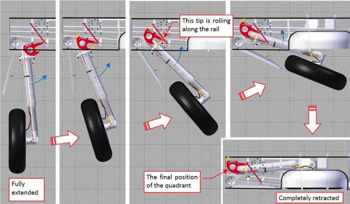 Figure 81-1 Landing gear retraction in the SBD Dauntless
In principle, it is simple: the landing gear leg rotates by 90⁰. However, the parts responsible for shock strut shortening during this movement increase mechanical complexity of this assembly. The figure above does not even show the deformations of the brake cable, which follows the shock strut piston movements.
For some scenes I will need the landing gear extended, while for the others – retracted. In practice, moving/rotating each part individually to “pose” my model would be a quite time-consuming task. That’s why I created a kind of “virtual mechanism”, which allows me to retract/extend the landing gear with a single mouse movement. In the previous post I already presented its results in this short video sequence. In this post I will shortly describe how I did it.
In general, I coupled some key elements (objects) of the landing gear using so-called constraints. For example, I connected the rotation of the landing gear leg with the movement of a special “handle” object. To do it, I used a Transform constraint, attached to the parent object (the axle of the retraction) of the landing gear leg (Figure 81‑2):
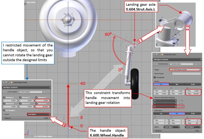 Figure 81-2 Coupling the landing gear leg with the handle object
I created an auxiliary (non-rendered) “handle” object (X.600.Wheel.Handle). The Transform constraint of the landing gear leg axle (0.604.Strut.Axis.L object) converts the handle linear movement into landing gear rotation. Thus when I shift the handle object upward, landing gear leg rotates, retracting into its place in the wing. To restrict the range of this rotation, I assigned to the handle object additional Limit Location constraint. It restrict its possible movement to a 40-unit long span along local Z axis.
The more detailed explanation of my methods for the “mechanization” of the landing gear would take too much space in this post. However, some years ago I published an article on this subject (in “Blender Art Magazine”):
 Figure 81-3 My article about rigging of the landing gear for the “Blender Art Magazine” (click to open)
To read this article, click the picture above or this link. I hope that this publication will explain you the general idea and typical implementation of such a “virtual mechanisms”. The format of this post allows just for a quick review of the SBD landing gear constraints (one picture per a subassembly).
Thus the next element coupled with the handle object (using another Transform constraint) is the landing leg cover (Figure 81‑4):
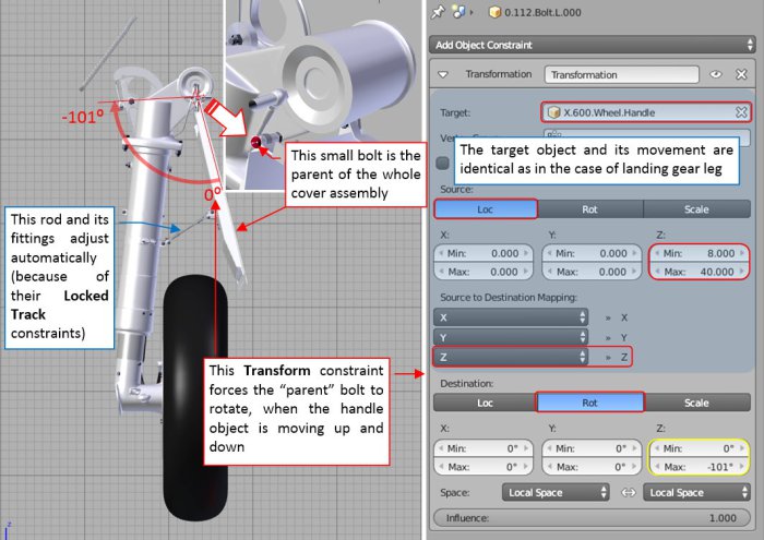 Figure 81-4 Retraction of the landing gear leg cover
In the previous post I added many bolt objects to the landing gear, and mentioned that some of them will have an additional use. So this is just such a case: I set the forward bolt of the cover hinge as the parent of the whole cover assembly. (Because it lies on its rotation axis). A Transform constraint, assigned to this bolt, forces it to rotate in response to the handle vertical movements. Note that the range of rotation of this cover (101⁰) is greater than the range of the landing gear leg rotation (90⁰).
Another Transform constraint converts the rotation of the quadrant object into movements of the shock strut piston (Figure 81‑5):
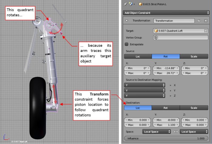 Figure 81-5 Shock strut piston movements
This relationship seems quite straightforward: when the quadrant rotates upward, the piston shifts up, when it rotates downward, the piston shifts down – as if they really were connected by the cable. Rotation of the quadrant is forced by its Locked Track constraint, which arm “tracks” the auxiliary (non-rendered) target object (the red, small circle in the figure above). Effectively, location of this quadrant target controls the shock strut position.
The full motion path of the quadrant target object contains an arc and a straight segment (Figure 81‑6):
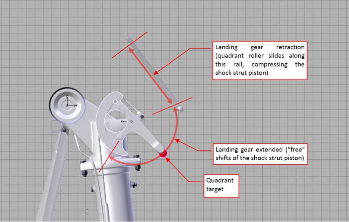 Figure 81-6 Motion path of the quadrant target object
The arc corresponds to possible piston positions for the extended landing gear (see this short video sequence). The linear segment corresponds to the forced compression of the shock strut during retraction, when the quadrant arm tip slides along the internal rail. (You can see this motion here, although in this video the path of the quadrant arm tip is not ideal).
I did not want to use the animation motion path here, because it creates a “deterministic” movement (“frame by frame”). Instead, I wanted a general solution, controlled by a handle object instead of the animation frames. Thus this is the most complex subassembly in this landing gear rig. I will describe it in two pictures: one for the extended landing gear (implementation of the movement along the arc), the other for the landing gear retraction (movement along the linear segment).
When the landing gear is extended, the rotation of the quadrant target is forced by its “grandparent” object. This is an Empty instance, named after the source of the original movement it mimics: X.Quadrant.Spring.Control (Figure 81‑7):
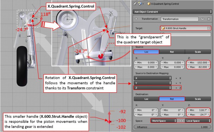 Figure 81-7 Implementation of the quadrant target movement (landing gear extended)
A Transform constraint converts the vertical movement of the additional handle object (X.600.Strut.Handle) into rotation between -24.7⁰ and +118⁰. There is another Empty object (0.607.Target.Left.Parent), attached (by the parent relation) to the X.Quadrant.Spring.Control. Simultaneously, 0.607.Target.Left.Parent is the parent of the quadrant target object. (The reason for such an indirect relationship will become clear in the next figure). When the landing gear is extended, this chain of “parent” relations forces the quadrant target object to move along the arc path when the handle object moves up and down. To not exceed the minimum and maximum angles of this movement (and in the effect – the lowest and highest shock strut piston position), the location of the handle object is restricted by a Limit Location constraint.
Note that this smaller handle is the child of the main handle, used for the landing gear retraction (X.600.Wheel.Handle). Note also that the Transform constraint that forces this rotation, evaluates the handle position in the World Space (Figure 81‑7, bottom right). This means that regardless of the position of the smaller handle, the shock strut will be fully extended after moving the main handle along the first few units along its way up. (So that I do not have to care about the initial piston position when I am starting landing gear retraction: it will set up itself).
During landing gear retraction the locations of the quadrant target, its parent, and “grandparent” become dispersed. Figure 81‑8 shows how it looks like in the middle of the main handle (X.600.Wheel.Handle) movement:
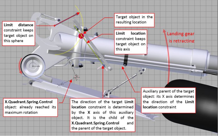 Figure 81-8 Implementation of the quadrant target movement (landing gear is retracting)
The parent (0.607.Target.Left.Parent) of the quadrant target object just “delivers” it to the rail line and stops there. (This is the end point of the rotation of its parent: X.Quadrant.Spring.Control object, as you can see in the previous figure). Then the quadrant target object is “dragged” by the landing gear retraction along the rail. I tried to obtain this effect by assigning it two constraints:
In theory, for such a constraint combination there is always just a single possible location of the target object (marked in the figure above). Unfortunately, it seems that Blender treats these constraint with certain “flexibility”. In the effect, the quadrant arm tip “sinks” into the rail. This effect is especially visible at the beginning of the landing gear retraction. Well, I tried hard but I could not find a better solution for this movement. Finally I concluded that I can left it in this state: this is a small part, which movements are partially obscured by the wing recess. When I need to make a close up, I can prepare a “deterministic” animation motion path for the quadrant target object.
The last rigged subassembly of this landing gear was the elastic brake cable. Because I used in this implementation another (better) solution than described in my article and book, I will discuss it shortly below (Figure 81‑9):
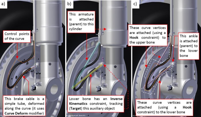 Figure 81-9 Solution for the elastic brake cables
First, as in my previous model, I formed the curve (Figure 81‑9a), that deforms the simple tubular mesh into the brake cable. (I used a Curve Deform modifier here). Then I created a simple armature consisting two bones: upper and lower (Figure 81‑9b). The armature object is attached (by a parent relation) to the strut cylinder. Thus the origin of the upper bone is also fixed in this way. I assigned to the lower bone an Inverse Kinematics constraint, and set its Target to an auxiliary Empty object at its end. This target object is indirectly (via the brake disk) attached to the piston. In the effect, this armature follows every piston movement in a natural way – like a pair of the torque scissors. Finally I attached subsequent curve vertices (control points) to the nearest armature bone (Figure 81‑9c). I also attached (via parent relation) the ankle object (at the bottom end of the brake) to the bottom bone. (So that it will follow its rotation). In the effect, the brake cable deforms when the shock strut piston is shifting, following its movement in a natural way. See this short video how it works.
In my previous model (the P-40B) I used for the same purpose a different, less effective combination of the constraints. I think that in the future I will always use the solution as in Figure 81‑9, not only for the brake cables, but also for the torque scissors (the SBD landing gear did not have such an element).
Finally, I applied my Handle Panel add-on to create a convenient landing gear controls among the Blender panels (Figure 81‑10):
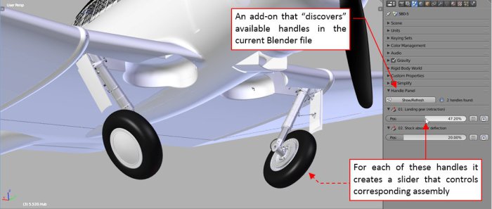 Figure 81-10 Retraction of the rigged landing gear
See this short video how it works. Now I can extend/retract the landing gear with a single mouse movement. I even do not have to know, where their handle objects are – the add-on will discover them automatically. (I just have to arrange them in the model space in a certain way – see the add-on description for details. This is a general utility, you can use it in your own Blender models).
The next part to recreate is the tail wheel assembly. I will report this step within two or three weeks.
In this source *.blend file you can evaluate yourself the current version of this model.
Advertisements Share this: