For a while now I have been intrigued with Integrated Light Sources i.e. NeoPixels. I knew nothing about them and with the coming of Christmas, I was inspired to take a closer look. I knew I would not have anything in place before Christmas 2017. But there is always next year.
DesignI wanted my solution to be compact and was imagining that it would be mounted close to the LED strip, perhaps only enclosed in a piece of heat shrink tubing. With this in mind, I knew I did not want to use an Arduino or similar. In fact, this was to be first and foremost a learning exercise. So I wanted to try my hand at picking my own microcontroller and creating my own driver.
I Must first give kudos to the sources of my research
- Adafruit NeoPixel Überguide
- TPS #31 Tutorial – on Programming the NeoPixel (WS2812) RGB LEDs
- Introduction to Microcontrollers – Driving WS2812 RGB LED
The research told me that I would need a processor with at least 8 MHz and since the LEDs need 5V, I figured, I could stick with that as the operational voltage for the microcontroller. Another design constraint was that I wanted a small (pin count) package. I am probably being biased but I had already narrowed my search amongst the Atmel ATTiny range of micro controllers. It was the ATTiny1614 that came to the top of the search for the properties shown below.
| In-system self-programmable Flash memory | 16 KB |
| SRAM | 2KB |
| RC Oscillator | 16/20 MHz |
I was actually curious about the internal 16/20 MHz oscillator, not requiring an external crystal and if this was going to cause any issues if the timing is as critical as some seem to imply.
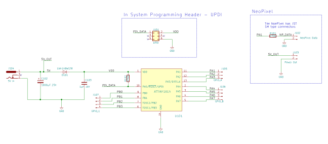
Schematic and LayoutThe circuit will be powered by a 5V power adapter. So I have not worried about extra regulation, apart from a 1 μF filtering capacitor and a diode to provide some protection against reversed connections. The circuit was quite simple in that it really is just the microcontroller and the rest is mainly connectors. Though I do take into consideration the tips from the Adafruit Überguide: Placing a 470 Ω resistor in series from the output pin of the microcontroller to the LED strip and adding a 1000 μF capacitor at the power input area.
 3d Visualisation
With so few parts, it was not too hard to keep the board small. I decided to expose all GPIO even though they were not going to be used. I figured that if this did not work as hoped for driving NeoPixels, I would at least have a quick’n cheap dev board.
For the layout, I gathered all the pins required for the NeoPixel strip to one end and flanked the other GPIO pin headers to each side. To keep the layout compact I opted to place the 1000 μF on the bottom layer.
I found it rather ironic that this is my first encounter with the 1-Wire protocol through the Integrated Light Source and in fact the ATTiny1614 is programmed with a 1-Wire protocol, via the Reset pin. So I had to figure out how this is implemented and connected so that I can program it. As it turns out, I was out of my league with my AVRISP MkII so l needed to upgrade to the AVR ICE. According to the description, the UPDI protocol also allows for debugging. This feature was missing on the AVRISP MkII, so I was curious about that too. On the layout, I don’t need much space for the programmer header since I use the solution provided by Tag-Connect.
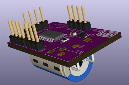
Assembly The assembled board
I deliberately chose a SOIC package for the ATTiny1614 as I find them quite easy to hand solder as with the 0805 passive components. I left the extra GPIO connectors off since they are not needed and mounted only the connector for the NeoPixel strip where I changed this to an angled connector.
The last piece to add was the power jack. For my other projects Power had always been delivered through a simple pin header. This time, I wanted something a little more substantial and chose a 3.5mm power jack.
Bringing the Board upBringing a board up for the first time is probably the most exciting or nerve racking part of a project. It can go in one of three ways: elation, disappointment or just simply “Huh?”. Even the later two can evolve into elation when the problem is found and the bodge is applied.
I used my usual approach – applying power with the lab power supply so I could monitor and control the current usage. Taking another tip from the Adafruit Überguide, the lab supply was activated first and then connected to the board to avoid any unwanted spikes. All was OK. Next was to power down and connect the programmer pin header. My usual steps are to start Atmel Studio and try to read the microcontroller properties. This time it was “disappointment”. It just would not read the properties. Going over the schematic, comparing with the documentation I could find, eventually I stumbled over a small comment:
“Since the RESET line is used for clocking the PDI, it is important to bypass or avoid any circuitry that can distort the clock signal during programming or debugging such as capacitors and external reset sources”
AVR042: AVR Hardware Design Considerations
 Back to Blinky
It is my usual practice to add a 100 nF capacitor on the Reset pin to ground – which is also described in the “AVR Hardware Design Consideration” guide. However with the 1-Wire operating over the Reset pin, there was obviously a clash. I removed the 100 nF capacitor and then I could read the ATTiny1614 properties. Elation.
I missed putting any form of indicating LED on the board so I rigged up LED on some breadboard to get the classic Blinky working to prove the connections and tool chain. While working on the Blinky I needed to work out what the default clock speed is and if it is really possible to run the ATTiny1614 at 20 MHz. From the datasheet, I understand that the processor can be clocked at 16 MHz or 20 MHz as selected by a fuse. The ATTiny properties were showing it is set to 20 MHz. The datasheet also revealed that, by default, the prescaler is activated and dividing the clock by 6. I just needed to basically disable the prescaler through the CLKCTRL.MCLKCTRLB register. However, I was not seeing any change when attempting to deactivate the clock – until, that is, I realised that the respective registers are protected and need to be “unlocked” before they can be changed. This is achieved by writing a predefined token to the CPU_CCP register.
CPU_CCP = CCP_IOREG_gc;
CLKCTRL.MCLKCTRLB = 0x00;
Once this was done, the way was clear to start working on the driver for the NeoPixel strip.
Creating the DriverIn principal the algorithm seemed straight forward. But I have to admit, I fell into a couple of traps. In working my way through the issues and studying the solution from Adafruit, I got to learn about integrating assembly code with C code through the asm function.
Along the way, I needed to understand what I was working with. A good approach I found was in Introduction to Microcontrollers – Driving WS2812 RGB LED where the required signal for the respective Highs and Lows are reduced to clock ticks.

If a ATTiny1614 clock cycle is 50 ns, then it is possible to work out the number of cycles needed for each data bit based on the information in the datasheet. This is where I fell into a trap. Based on the documentation I was reading, I assumed the timing for these LEDs was the same. This is not the case. After a while of unsuccessful attempts, I went back on my order for my NeoPixel strip and called up the datasheet to find I was not working with the WS2812 after all but the SK6812!
The table below shows the relative difference between the devices. When focusing the timing on one device, based on the micro controller clock period length, it is possible to be out of specification for the other device. This where my oscilloscope was invaluable where I could see exactly what it was I was delivering to the NeoPixels.
|
Data Bit |
WS2812 |
SK6812 |
|
HIGH |
HI:700ns, LO:600ns HI:14c, LO:12c |
HI:600ns, LO:600ns HI:12c, LO:12c |
|
LOW |
HI:350ns, LO:800ns HI:7c, LO:16c |
HI:300ns, LO:900ns HI:6c, LO:18c |
|
RESET |
> 50 μs > 1c |
> 80 μs > 1.6c |
In my version of the driver, I simply allocate an array of uint8_t to hold each colour byte for each pixel. The work is performed up front to get the colour bytes in the correct location rather than swapping from one array to another when sending the data to the strip. This way the buffer is parsed as-is.
The C code part just sets up some variables and reads the port to be used for the LED strip. Since there is no other activity on the port, it is only read once.
The assembly part checks the most significant bit of the current data byte. If it is set, it jumps to “do_HI” which raises the output pin for 12 cycles and then low for another 12 cycles. If the bit is cleared, it will jump to “do_LO” where the output pin is raised for 6 cycles and held low for 18 cycles. Trading simplicity for elegance, I inserted NOP instructions to get the desired number of cycles. The second stage of the data bit signal is the tough one to keep accurate. After the output pin is held high and then brought low, other checks are made to see if it has reached the last bit in the data byte or if it has reached the end of the buffer. Each of these cost cycles. Luckily, the second part of the signal does not appear so critical than the first part.
void neopixel_show() { volatile uint16_t idx = neopixel_buffer_size; // Loop counter volatile uint8_t *port; volatile uint8_t *ptr = &buffer[0], // Pointer to next byte byte = *ptr++, // Current byte value hi, // PORT Output bit HIGH lo; // PORT Output bit LOW volatile uint8_t bit; // Initialising the variables hi = VPORTA_OUT | pinMask; lo = VPORTA_OUT & ~pinMask; bit = 8; // Create a pointer to PORTA port = &VPORTA_OUT; // Initialise PORTA to LOW VPORTA_OUT = lo; asm volatile( "neo_start:" "\n\t" "st %a[port], %[hi]" "\n\t" // PORT = Hi "sbrc %[byte], 7" "\n\t" // Skip the next operation if bit 7 is clear "rjmp do_HI" "\n\t" // Jump and Do the HI case "do_LOW:" "\n\t" // At 3 cycles. For LOW, still need 3 for HI and then 18 LOW "nop" "\n\t" "nop" "\n\t" "st %a[port], %[lo]" "\n\t" // PORT = Low (Finish of 6 Hi cycles- start the 18 LOW) "nop" "\n\t" "nop" "\n\t" "nop" "\n\t" "nop" "\n\t" "nop" "\n\t" "nop" "\n\t" "nop" "\n\t" "nop" "\n\t" "nop" "\n\t" "nop" "\n\t" "rjmp next_bit" "\n\t" "do_HI:" "\n\t" // At 3 cycles. For HI, still need 9 for HI and then 12 LOW "nop" "\n\t" "nop" "\n\t" "nop" "\n\t" "nop" "\n\t" "nop" "\n\t" "nop" "\n\t" "nop" "\n\t" "nop" "\n\t" "st %a[port], %[lo]" "\n\t" // PORT = Low (Finish of 16 Hi cycles- start the 9 LOW) "nop" "\n\t" "nop" "\n\t" "nop" "\n\t" "rjmp next_bit" "\n\t" "nop" "\n\t" "next_bit:" "\n\t" // This section costs 3 - 5 cycles "dec %[bit]" "\n\t" // bit-- "breq next_byte" "\n\t" // branch if(bit == 0) (from dec above) "rol %[byte]" "\n\t" // Roll the byte left one bit. "rjmp neo_start" "\n\t" // Jump to start for the next bit "next_byte:" "\n\t" // This section costs 9 cycles! "ldi %[bit], 8" "\n\t" // Set bit = 8 "ld %[byte], %a[ptr]+" "\n\t" // Set byte = *ptr++ "st %a[port], %[lo]" "\n\t" // PORT = lo "sbiw %[count], 1" "\n\t" // idx-- "brne neo_start" "\n" // if(idx != 0) -> (next byte) : [port] "+e" (port), [byte] "+r" (byte), [bit] "+r" (bit), [count] "+w" (idx) : [ptr] "e" (ptr), [hi] "r" (hi), [lo] "r" (lo)); } Conclusion and Next StepsI was very happy to get the NeoPixels working with the ATTiny1614 and really feel I have learned a few things on the way. I am impressed with the ATTiny1614 and can imagine to use it again in coming projects especially over the ATTiny20 I used previously. The ATTiny1614 has more Flash and it has EEPROM which I missed on the ATTiny20. I am not so convinced of the debugging capability through the UPDI. The execution seem to, on occasions, simply run-away rather than stepping to the next instruction. I probably need more practice with using such tools before saying too much as my understanding of debugging protocols is very basic.
A project like this is never complete. Or at least the proof of concept is done and now I can find some applications. There are a couple of improvements to the firmware which would include
- Assembly Module – Create an assembly file rather than using the asm function. It is not possible to step through the asm function.
- Cleaning up my neopixel.h and neopixel.c to be a bit more generic instead of hardcoding PORT_A and PIN_1.
- Working out some more animations
https://github.com/SteveMayze/AdventSternla
Advertisements Share this: